Introduction: Easy IoT Weather Station With Multiple Sensors
A weather station is a fun project that teaches you a ton about electronics with the added benefit being an actually useful little device. The project requires a bunch of cheap parts and sensors totaling less than $15, and the whole thing ends up fitting in your hand. The station creates a web site that monitors temperature, dew point, humidity, pressure, light index, and rain (Thingspeak channel). It’s a pretty easy set up, and you’ll just need some basic electronics skills to get it going.
There are some other NodeMcu or ESP8266 weather stations published on the web. Nevertheless they do not include the sensors I used and often are programmed in the more difficult language: LUA. This weather channel has got the following (unique) characteristics:
- NodeMcu board (V0.9 or V1.0), programmed with arduino IDE (easy);
- Streaming data to Thinkspeak (also easy!);
- DHT11/22 sensor;
- BMP180 sensor;
- Rain sensor;
- Light sensor;
- Piezzo indicating buzzer;
- Flashing indication led.
This channel will stream the following sensor data to a Thingspeak channel:
- Temperature DHT11/22;
- Temperature BMP180;
- Humidity DHT11/22;
- Pressure BMP180;
- Dew point temperature DHT11/22;
- Altitude BMP180;
- Light intensity LDR;
- Rain value.
The specific materials needed for this project are mentioned per step. General materials needed are:
- Breadboard;
- Perfboard;
- NodeMCU V0.9 or 1.0;
- Some wires;
- Micro USB to USB cable;
- 2 '1N4001 1A 50V Diodes'
- 3 '10K resistors'
I estimate the costs of the project around 15$. (NodeMCU=4,76$, DHT22=3,10$ OR DHT11=1$, BMP180 = 3,50$, Rain sensor = 0.99$, additional materials such as perfboard, wires, 2 diodes, 2 resistors and 1 LDR, I estimate around 4$)
Step 1: The NodeMcu Board
As I am a newby, I bought the NodeMcu board for less than 6$, more or less per exident. I was looking for a board that could connect my projects to the internet. The NodeMcu board did look a lot like an arduino and therefore it felt very familar. At that time I had no idea of the big advantages of the board.
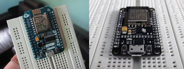
The NodeMcu board is in fact an arduino with a wifi shield. You can reconise this shield by the metal plate on top of it. This wifi shield is called the esp8266. The shield can be bought and used as an individual controler, a well known version is the esp8266 V1 which has only got 2 digital pins. The later version (one of them is placed on top of the NodeMcu board) do have more digital pins.
The big advantage of the NodeMcu board is that the board can be programmed in the arduino environment: arduino IDE. Also, the board consists of a 5 volt step down converter. You can safely connect the board by USB to your computer without having to buy a 3.3 volt stepdown module.
If you want to buy a NodeMcu board you can buy either the 0.9 version or the 1.0 version. The only difference I know is that the 0.9 version is wider than the 1.0 version. Yyou can not use the 0.9 version on a broadboard and plug in wires next to it.

I found a lot of tutorials on the internet where they programmed the board with LUA software. As I never used this software before I preffered to stay with the arduino IDE software.
Programming the nodeMCU with arduino is easy!
Simply open arduino IDE, the latest version (I use 1.6.6). Go to 'file' and click on 'preferences'. Add the following link in the field 'additional board URL':
http://arduino.esp8266.com/stable/package_esp8266c...
After this you can restart the software and you must be able to select the board in the board manager (V1.0 or V0.9).
Pins of the NodeMcu
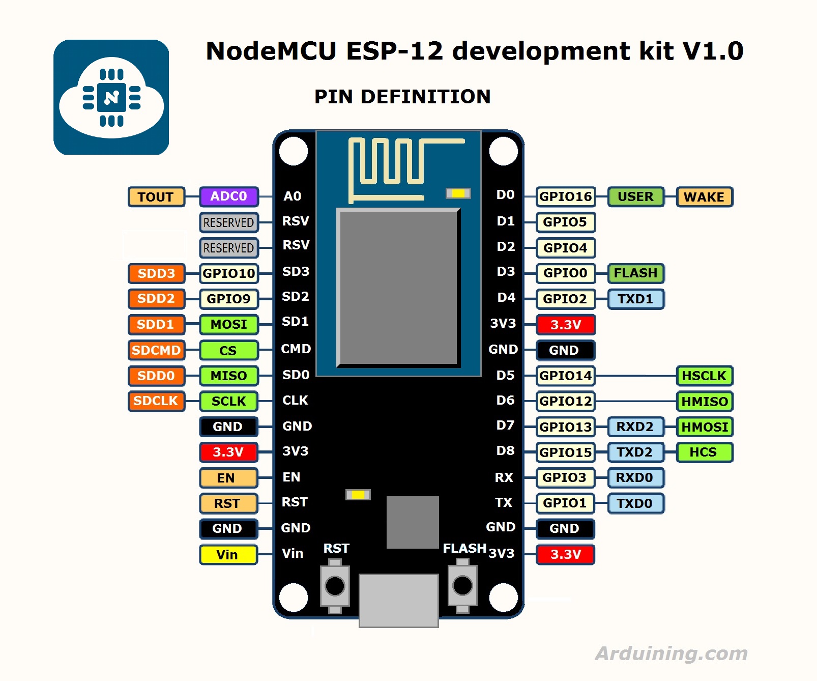
A small note: when you are programming an NodeMCU board, the pin layout is slightly different from an arduino board. Use the image below to compare the pins. If you mention an GPIO pin in the sketch for the NodeMCU, you have to connect the wire to the pin indicated in the picture below. (google: 'NodeMCU pin map')

For example: If you want to connect some sensor to D5, you have to mention pin 14 in your arduino code. In the code below and the corresponding Fritzing visualisation, the connections are already adjusted.
Step 2: Connecting to Thingspeak
As we are going to push our data to Thingspeak we have to make an account. Thingspeak is a cloud service. It is great, easy and looks realy cool! Next to this, Thingspeak provides several options for interaction with your data such as Thingtweet, Thinghttp etc.
Simply go to thingspeak.com and make an account. Fill in at least the first and second field in the settings. If you connect a temperature and humidity sensor such as described in the next step, fill in 'temperature' in field 1, 'humidity' in field 2 and 'dew point' in field 3. If you want to connect other sensors such as the BMP sensor, rain sensor, LDR, simply do the same forthe rest of the fields.
You can find a key that you have to mention in your arduino sketch under the tap 'API key'. This key is necesarry to connect the arduino to the Thingspeak channel. See step 4 :)
Step 3: Connecting the Sensors
I can recomment you to connect the sensors one after the other, starting with the DHT11/DHT22 sensor. Once a sensor is working properly you can go on and add the next sensor.
The DHT11/22
This is a simple sensor to start with! The DHT22 is slightly more accurate compared to the DHT11 but is less costly. I started with the blue DHT11 but get enthusiastic and bought the white DHT22 soon after. As you can see in the image above I add all the sensors in the broadboard next to the NodeMcu.
Connecting the DHT11 or DHT22 sensor is very easy. Make sure you check the following:

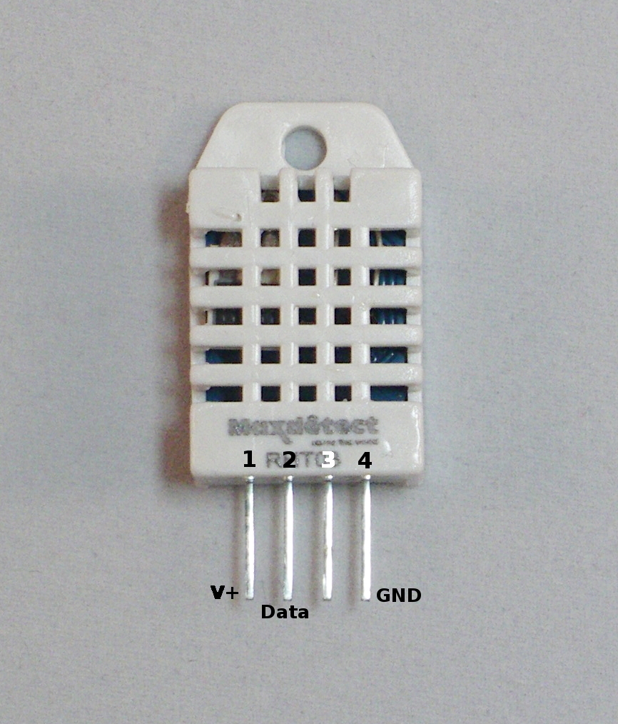
If your sensor is on a small board, there is already a resistor between pin 1 and 2. The board with the DHT11/DHT22 has only three pins. If not (as presented in the picture), add a 10K resistor between the first and the second pin. Connect the first pin to the 3.2 volts (presented on the board) and the 4th pin to the ground. Connect the second pin to digital pin 4 (D$) of the NodeMcu board.
If you look closely you will see that the D4, 5V and ground pin on the NodeMcu board are all next to eachother! When you make use of a DHT sensor on a small board you can easily prick the sensor in the broadboard next to the NodeMcu as the pins will match!
The BMP sensor
The BMP sensor meassures the temperature and the air pressure. Yes, we already have a temperature sensor added in the previous step but not an air pressure sensor. Connect the power pin to the 3.2 volt line of the NodeMCU and the ground pin to the ground of the NodeMCU. The SCL has to be connected to D1 and the SDA to D2.
The Rain sensor and Light sensor
This is a tricky part as the NodeMCU has only one analog pin (see image, buttum left). We can solve this problem by multiplexing the analog pins. With the help of two diodes and two GPIO pins we power both sensors in sequense. I have written a seperate instructable about this. Please click here. The instructable is based on an arduino board. Since the NodeMCU is programmed with arduino IDE this will be no problem.
As you can see the rain sensor is powered by pin D7 (GPIO13). The LDR is powered by pin D8 (GPIO15).
A small node on the rain sensor used in this project. The rain sensor was dilivered with a small module. This module is not required for the rain sensor to work as we want to read the analog value. The reason people use these modules is that connection to digital pins of the microcontroler is possible. The onboard potentiometer sets the value in order to pull the digital pin of the microcontroller high or low.
Step 4: Coding
As I am not very good in programming I tried several sketches availible on the internet. I found out that most of the sketches where written in LUA language and therefor useless for me. An other thing I found is that when you find a sketch for a seperate esp8266 shield (one of them is on top of the NodeMcu) it is possible to use this sketch on the NodeMCU without any problems. Ok, this should sound stupid to you, but I realy didnt know that!
I found a good sketch for temperature and humidity on this website. As one can see this sketches is made for the esp8266V1.0 (only the wifi shield with 2GPIO pins) but workes on the NodeMcu board. The library of the ESP8266WiFi.h is automaticly downloaded when you add theNodeMcu board, the DHT library you can simply download by using the inbuild library manager. I found that when using the DHT library (and not the DHT11 library) it doesnt matter which sensor you use, the DHT22 or the DHT11! Simply change everywhere where DHT11 is written in the text into DHT22. Great!
The sketch from this website served as basis for the sketch I developed and is given below. I simply started with the DHT22 sensor to push the temperature and humidity to thingspeak whereafter I added the BMP sensor, rain sensor and LDR sensor. If you compare the sketch above with the sketch below you will see how to add aditional sensors!
After I added all the sensors I discoverd that you can derive the dew point from the temperature and the humidity. It is also possible to retreave the alltitude from the temperature and the air pressure, althrough this is from less importance for a weather channel it is fun. I added the formula for the dew point and the alltitude in the arduino sketch.
- Change the apiKey with the one of your account of thingspeak
- Add the 'ssid name' of your wifi network. This is simply the name you see when you click in the right bottum corner of you screen.
- Add the password of this wifi network
If you uploaded the sketch you can verify in the serial monitor how it works. Simply open the monitor by pressing CNTR + M.
Step 5: Getting Everything in One Box
I love to use old screw boxes for project enclosures as they have the perfect size for microcontrollers and are watertight. The rain sensor fitted perfectly on top of the screw box I used. The DHT sensor and the BMP sensor I positioned on the side of the box. I covered both sensors with some multiplex so that rain could not invluence the readings.
A small update: I see that the temperature (see my thingspeak channel) is a bit on the high side during the day. I think this is the result of the screw boxes that have limited mass and heat up quickly. Mabey a more solid structure (from wood or bricks) will give more accurate readings.
update: Mabey it is not a good idea to put it in a screw box. I thought that they would be watertight but it appeared to be different. See last picture.
Step 6: Getting Cool Gauges
Thingspeak has lots of plugin options. One of them is that it is possible to make gauges and publish them on your website. Thingspeak will automaticaly generate a code for the gauges. It is possible to adjust the gauges (change the colors, numbers, scale etc.) by adjusting the code. Unfortunately viewing the gauges is only possible in the 'private view' tab of Thingspeak. If you link the gauges to your private website (such as I did) by using an iframe you have to be logged in to Thingspeak to be able to view the gauges.
In my gauges I adjusted the position of the colors. I also added the collor green. Please copy the following code in the HTML section, the CSS section and the Javascript section of Thingspeak. (The code below I use to view the temperature)
Step 7: Extra Features
I added a piezo buzzer that indicates when the board is connected to the wifi. The piezo buzzer is not included in the sketch presented above. Please contact be if you have problems connecting a piezo buzzer.
An other future I added is a flashing led. On the NodeMcu one can find an onboard led that flashes everytime data is send. I demolished the led with a soldering iron and soldered wires on the old connection points of this led before adding a 4mm led. This led tells me when data is send. This extremely easy when the NodeMCU is positioned inside the screw box.
Step 8: Have Fun
Have fun building and learning! Please let me know what you think of this instructable. I would love to make some improvements if necesarry.
Regards,
Vincent

First Prize in the
Sensors Contest 2016

Second Prize in the
Internet of Things Contest 2016


