

Introduction: Experimenters Guide for Arduino As Performed at OIT


Resources
Adafruit ARDX - v1.3 Experimentation Kit for Arduino
Experimenters Guide for Arduino (PDF)
Bread Board Layouts (PDF)
Arduino Tutorial Bundle (Instructable)
This Arduino Tutorial is going to be very similar to the Arduino Tutorial Bundle Instructable but because we are working on this in our class I figured Instructables would be a good place to organize our YouTube videos and add some more help. To sum up the difference between the two tutorials, Arduino Tutorial Bundle is the basically the book that is linked in the references an includes pictures steps and the code. This instructable has the steps I used to when following the Experimenters Guide, and my classmates YouTube videos.
-----------------------------------------------------
General Information:
My first problem was that Windows 8 did not install the driver for the arduino. Windows 8 gave me an error message saying that the driver was unsigned. To get round the new windows 8 security checks I followed THIS guide. Basically use Advanced Startup to start with Disable Driver signature Enforcement. our your windows 7 PC
I used a Pin to Poke a hole through the paper where the wires should go so that the holes in the bread board are easier to find and its nicer on the parts.
The second half of the kit and some of the less complicated ones don't have any components on the left side of the board.I aligned the grid paper to the right side of the bread board with only the right pins to hold it.
To store the extra pieces from the kit and to keep the resistors organized i placed everything on a spare bread board.
the .gif pictures don't align up exact. this is my attempt at making 3d stereoscopic gif pictures.
Step 1: CIRC-01 Blinking LED
Assembly is fairly straight forward, if you use the bread board templates the holes line up close enough. The little boxes that say [ to .... ] get plugged in the arduino somewhere. for example [ to pin 13 ] is plugged into pin 13.
The code says the led is on pin 13 then it runs a loop where it sets the led to be on then off.
Basic instructions are at '''CIRC-01''' - Getting Started - (Blinking LED)
Instead of writing all the code from scratch you can copy the code from the PDF or http://ardx.org/CODE01.
3 upload the program
file> upload should do the trick if, not go to tools> serial port and try a different channel.
YouTube Videos
Step 2: CIRC-02 8 LED Fun

On the LEDs remember that the longer leg is positive. The legs on the resistors bend very easily so it might help to to use a pencil to poke a hole in the paper then sticking in the resistors. This uses up most of the digital pins out.
The code is much longer then the first lab. It starts by designating the pins. then it states the different loops, one loop starts each light one at a time and the other has a loop inside it , they both do the same thing but with a loop there is much less code.
Basic instructions are at '''CIRC-02''' - Multiple LEDs - (8 LED Fun)
copy the code from http://ardx.org/CODE02
Step 3: CIRC-03 Spin Motor Spin


On my circuit i did not need the optional capacitor.
I attached a piece of blue tape to the motor so that I could see that it spun.
The legs of the transistor are not labeled but if you are using the breadboard layout just place it in the same direction as its drawn.
The codes say to use pin 9 then goes to say if pin 9 is + or - 5 volts. Below it uses speed and time variables to control the motor.
Basic instructions are at '''CIRC-03''' - Spin Motor Spin - (Transistor & Motor)
copy the code from http://ardx.org/CODE03
Step 4: CIRC-04 a Single Servo


This project might be easier then the first. Most the electronics for the servo motor are inside it and it is very quick to plug into the bread board. When the motor is running it does make a funny clicking sound but that is from the code.
The code says to rotate 1 degree then wait 15 milliseconds before turning again.
Basic instructions are at '''CIRC-04''' - A Single Servo - (Servos)
copy the code from http://ardx.org/CODE04
Step 5: CIRC-05 8 More LEDs


This is the hardest circuit to assemble so far, if you wanted to make an LED cube it would probably be in this method of controlling the LEDs.
The Arduino and the shit registers work together. The shift register act as extra pins on the arduino and do what the arduino tells it to. the shift register uses the serial communication link to talk with the arduino.
Basic instructions are at '''CIRC-05''' - 8 More LEDs - (74HC595 Shift Register)
copy the code from http://ardx.org/CODE05
Step 6: CIRC-06 Music
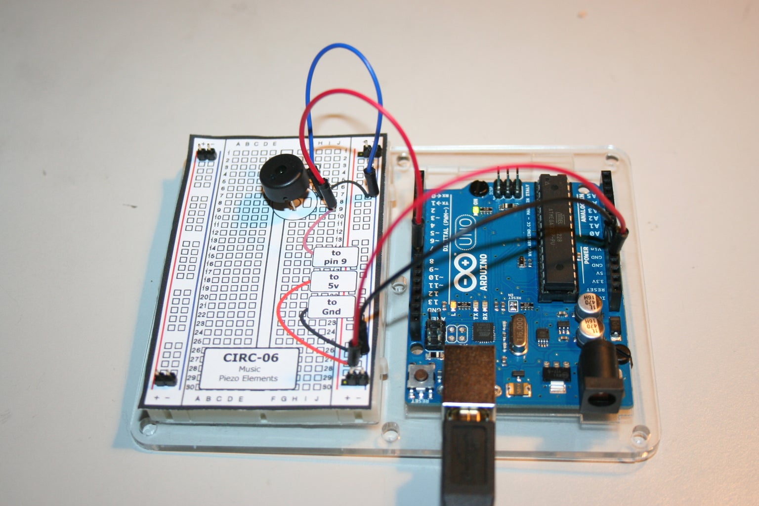

Most of this lab is in the code. To assemble the circuit it is easy just 4 wires and the piezo. The code states what frequency to use for each note. then it says the order of notes to play and how may beets each note is.
see EXTRA LAB 6B on how to play a different song
Basic instructions are at '''CIRC-06''' - Music - (Piezo Element)
copy the code from http://ardx.org/CODE06
Step 7: CIRC-07 Button Pressing


the interesting thing about this circuit is that the push button is used the easy way, directly in line with the light. the arduino reads the voltage off the button then if the button is being pressed it turns on the light and if not the light is off.
Basic instructions are at '''CIRC-07''' - Button Pressing - (Push Buttons)
copy the code from http://ardx.org/CODE07
Step 8: CIRC-08 Twisting


The trick is that the yellow wire goes all the way across the arduino board to where A0, the analog pin, is.
Basic instructions are at '''CIRC-08''' - Twisting - (Potentiometers)
copy the code from http://ardx.org/CODE08
Step 9: CIRC-09 Lights


the photo sensor changes the resistance but the arduino an only read the voltage so a current is run across the sensor and when it changes it knows how to din the light. the light isn't really dimming it is being blinked at different rates. it is easier to see the blink rate by shaking the arduino.
Basic instructions are at '''CIRC-09''' - Light - (Photo Resistors)
copy the code from http://ardx.org/CODE09
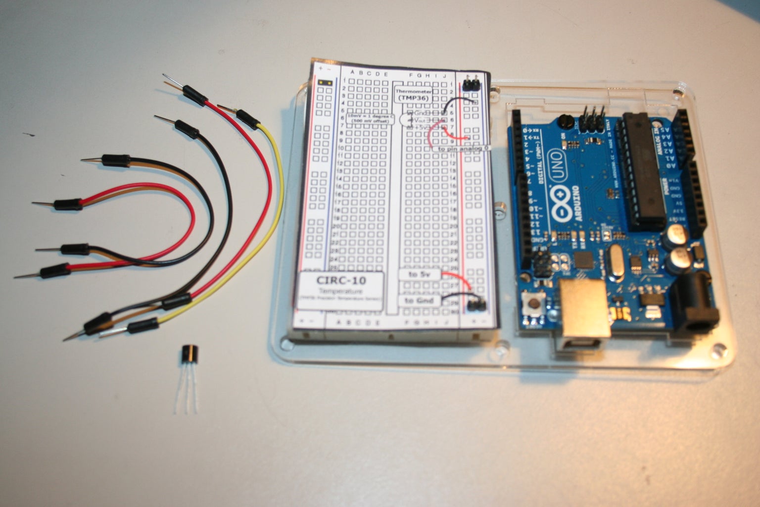
Step 10: CIRC-10 Temperature
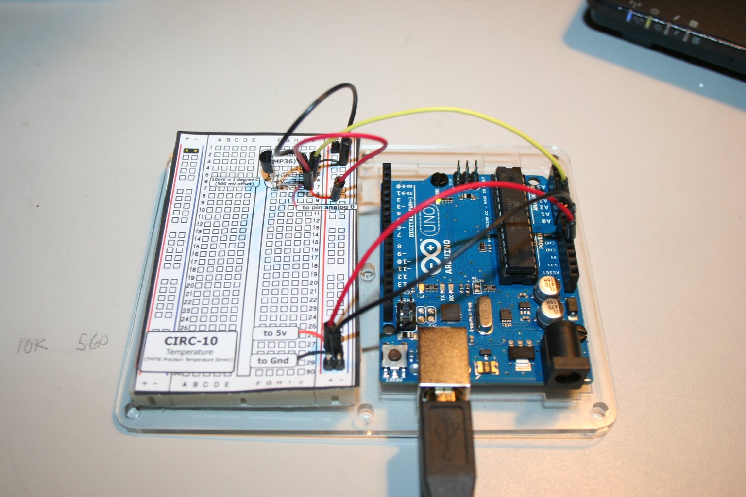


Of all of the Yank's archaic measuring systems, Fahrenheit is the best. How is a hot day only 40 degrees? That will never sound hot to me. Fahrenheit was made first, there are 180 degrees between water freezing and boiling, and it wasn't made by Lord Kelvin. See this ehow.com (ya i know ehow sucks but it agrees with me this time) post.
Basic instructions are at '''CIRC-10''' - Temperature - (TMP36 Precision Temperature Sensor)
copy the Celsius code from http://ardx.org/CODE10
or if your awesome the Fahrenheit code is is below
EXTRA LAB CIRC-10B BETTER TEMP
/* ---------------------------------------------------------
* | Arduino Experimentation Kit Example Code |
* | CIRC-10 .: Temperature :. (TMP36 Temperature Sensor) |
* ---------------------------------------------------------
*
* A simple program to output the current temperature to the IDE's debug window
*
* For more details on this circuit: http://tinyurl.com/c89tvd
*/
//TMP36 Pin Variables
int temperaturePin = 0; //the analog pin the TMP36's Vout (sense) pin is connected to
//the resolution is 10 mV / degree centigrade
//(500 mV offset) to make negative temperatures an option
/*
* setup() - this function runs once when you turn your Arduino on
* We initialize the serial connection with the computer
*/
void setup()
{
Serial.begin(9600); //Start the serial connection with the copmuter
//to view the result open the serial monitor
//last button beneath the file bar (looks like a box with an antenae)
}
void loop() // run over and over again
{
float temperature = getVoltage(temperaturePin); //getting the voltage reading from the temperature sensor
temperature = ((temperature - .5) * 100)*1.8+32; //converting from 10 mv per degree wit 500 mV offset
//to degrees ((volatge - 500mV) times 100)
Serial.println(temperature); //printing the result
delay(1000); //waiting a second
}
/*
* getVoltage() - returns the voltage on the analog input defined by
* pin
*/
float getVoltage(int pin){
return (analogRead(pin) * .004882814); //converting from a 0 to 1023 digital range
// to 0 to 5 volts (each 1 reading equals ~ 5 millivolts
}
Step 11: CIRC-11 Larger Loads


wow the "what were doing" in the book really romanticized the "Relay", but i guess for electrical engineers a relay is really physical. Or else I'll be eating my words when I Love them ( I'll add it here for sure if I do). By the way I just got the killers 2012 album, Battle Born, and I really like it, listened to it 4 times in a row now, i think i like Mis Atomic Bomb Best.
Back to the lab, there is a lot of wires in this one and the DPDT is in the same rail as the positive side of the LED. Aka right where it shows the wire going to, not to the ardrano. See this PIX its a blue wire.
In the bottom left hand corner there are a bunch of wires overlapping don't for get to send 2 to to the Arduino , +5v and GND, and 2 across the bread board to the other positive and ground rows.
since its hidden in the book one light should blink for a second then the other.
Basic instructions are at '''CIRC-11''' - Larger Loads - (Relays)
copy the Celsius code from http://ardx.org/CODE11
Step 12: CIRC-12 Colorful Light


I'd say that the long leg of the LED is common, or I can just pay attention to the template, it agrees with me.
Wow this is awesome its such a smooth transition between colors and the LED is bright. If I only had 100 multi-colored LEDs to make a TV (and a few Shift Registers). or make the LED CUBE out of these and have a 3d tv.
Basic instructions are in the Experimenters Guide for Arduino (PDF)
copy the code from http://ardx.org/CODE12
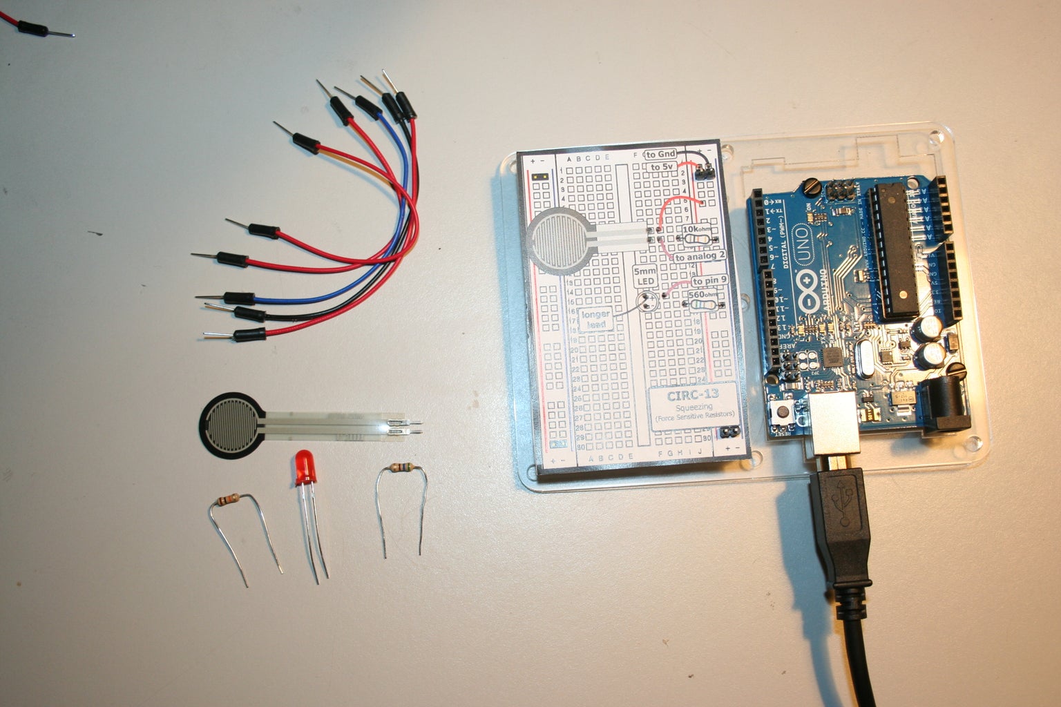
Step 13: CIRC-13 Squeezing

WOW the last lab already.
this use the analog 2, all the way across the board, again.
I think it works real well, already thinking of uses for this kind of switch, maybe in my boxing gloves, :)
Basic instructions are in the Experimenters Guide for Arduino (PDF)
copy the code from http://ardx.org/CODE13A
Step 14: EXTRA LAB CIRC-13B


Extra Lab 1
This lab uses the Potentiometer to control the servo location.
the Potentiometer is plugged into the analog input A0, and the Servo is plugged into the data pin 9. It reads the voltage change caused by the potentiometer to tell the servo what position it needs to be in.
see attached picture for wiring diagram
copy the code from http://www.ardx.org/src/circ/CIRC13-code-SPAR.txt
Step 15: EXTRA LAB CIRC-06B

the new notes are eeggeeee, pause. The edited code is below. I had to say that now there is 9 notes, state the order of notes and leave a space for the pause, on the line below I had to say the beet length of each note. Then last I had to slow the speed of the song by reducing the tempo.
* (cleft) 2005 D. Cuartielles for K3
*
* This example uses a piezo speaker to play melodies. It sends
* a square wave of the appropriate frequency to the piezo, generating
* the corresponding tone.
*
* The calculation of the tones is made following the mathematical
* operation:
*
* timeHigh = period / 2 = 1 / (2 * toneFrequency)
*
* where the different tones are described as in the table:
*
* note frequency period timeHigh
* c 261 Hz 3830 1915
* d 294 Hz 3400 1700
* e 329 Hz 3038 1519
* f 349 Hz 2864 1432
* g 392 Hz 2550 1275
* a 440 Hz 2272 1136
* b 493 Hz 2028 1014
* C 523 Hz 1912 956
*
* http://www.arduino.cc/en/Tutorial/Melody
*/
int speakerPin = 9;
int length = 9; // the number of notes
char notes[] = "eeggeeee "; // a space represents a rest THIS IS THE PART I CHANGED
int beats[] = { 2, 2, 1, 1, 2, 2, 1, 1, 1 }; // THIS IS THE PART I CHANGE
int tempo = 200; //THIS IS REDUCED FORM 300 SO THAT IT PLAYS SLOWER
void playTone(int tone, int duration) {
for (long i = 0; i < duration * 1000L; i += tone * 2) {
digitalWrite(speakerPin, HIGH);
delayMicroseconds(tone);
digitalWrite(speakerPin, LOW);
delayMicroseconds(tone);
}
}
void playNote(char note, int duration) {
char names[] = { 'c', 'd', 'e', 'f', 'g', 'a', 'b', 'C' };
int tones[] = { 1915, 1700, 1519, 1432, 1275, 1136, 1014, 956 };
// play the tone corresponding to the note name
for (int i = 0; i < 8; i++) {
if (names[i] == note) {
playTone(tones[i], duration);
}
}
}
void setup() {
pinMode(speakerPin, OUTPUT);
}
void loop() {
for (int i = 0; i < length; i++) {
if (notes[i] == ' ') {
delay(beats[i] * tempo); // rest
} else {
playNote(notes[i], beats[i] * tempo);
}
// pause between notes
delay(tempo / 2);
}
}


