Introduction: Extra I/O Pins for Your Arduino Uno
Making a cool project and ran out of pins? NO..... don't worry there are two solutions one is make our own shield that will add extra 16 I/O pins to your project (follow this tutorial). Or you can check out this amazing kick-starter campaign to make a 64 I/O arduino shield. Or do both!
Step 1: Shopping List
To make this project a success you'll need:
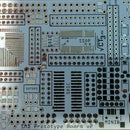
prototype shield
stackable header or pin header
some wire
resistors and leds
and the most importantly some
MCP23017 chip
Step 2: Soldering
now is the time solder it up.
Have a look at pinout picture or full datasheet
First place the chip (look at the pictures to see where pin one should go)
Then solder up the ground (brown wires):
Pin 10 is ground, then pins 15,16,17 are to set the address (by choosing 5v or gnd) put them all ground for this time, if you plan to add more you will need to change configuration.
Then Solder 5v (orange wires)the important one is pin 9. the rest wires in the pic go to LED one for power, another from pin 21 (to show that it works).
and most importantly wire SDA (pin 13) to A4 (on arduino uno) and SCL (pin 12) to A5 (arduino uno). for other arduino boards read specifications to find the SDA and SCL pins.
Another important thing to add is two resistors value between 4.7k and 10k between SDA SCL and 5v.(see schematics). its is not necessary (as arduino has some pull up resistors but not very strong) but if you want to make to reliable i would suggest adding them.
Now you have 16 extra I/O (pins 1 to 8 and 21 to 28).
Step 3: Programming Time
Wire library is needed to use I2C (included in standard arduino), but its not very easy to use. To make its simpler I use IOsheld Library it enables easy to use commands to control you project. Just save it in the libraries category.
and load the sample code and its done.
// Example code for 64shield Library
// Works with Centipede Shield or MCP23017 on Arduino I2C port
#include <Wire.h>
#include <IOshield.h>
/* Available commands
.digitalWrite([0...127], [LOW...HIGH]) - Acts like normal digitalWrite
.digitalRead([0...127]) - Acts like normal digitalRead
.pinMode([0...127], [INPUT...OUTPUT]) - Acts like normal pinMode
.portWrite([0...7], [0...65535]) - Writes 16-bit value to one port (chip)
.portRead([0...7]) - Reads 16-bit value from one port (chip)
.portMode([0...7], [0...65535]) - Write I/O mask to one port (chip)
.pinPullup([0...127], [LOW...HIGH]) - Sets pullup on input pin
.portPullup([0...7], [0...65535]) - Sets pullups on one port (chip)
.init() - Sets all registers to initial values
Examples
IO.init();
IO.pinMode(0,OUTPUT);
IO.digitalWrite(0, HIGH);
int recpin = IO.digitalRead(0);
IO.portMode(0, 0b0111111001111110); // 0 = output, 1 = input
IO.portWrite(0, 0b1000000110000001); // 0 = LOW, 1 = HIGH
int recport = IO.portRead(0);
IO.pinPullup(1,HIGH);
IO.portPullup(0, 0b0111111001111110); // 0 = no pullup, 1 = pullup
*/
IOshield IO; // create 64shield object
void setup()
{
Wire.begin(); // start I2C
IO.initialize(); // set all registers to default
IO.portMode(0, 0b0000000000000000); // set all pins on chip 0 to output
//TWBR = 12; // uncomment for 400KHz I2C (on 16MHz Arduinos)
}
void loop()
{
for (int i = 0; i < 15; i++) {
IO.digitalWrite(i, HIGH);
delay(10);
}
for (int i = 0; i < 15; i++) {
IO.digitalWrite(i, LOW);
delay(10);
}
}
If you want even more pins check out my kick-starter campaign to create 64 I/O arduino shield! yes that 64 extra pins on a normal size arduino shield... madness..


