

Introduction: PS1 Controller Joysticks With Arduino

Please let me know what you think or if you have questions/criticism for me! I'm always looking to learn new things.
Required materials:
~ Playstation 1 controller
~ Soldering Iron
~ Solder
~ Knife
~ Wire strippers/cutters
~ Electrical Tape
~ Small Phillips head screwdriver
~ Two mid-value resistors (for pushbutton cicuits)
~ Third Hand (not absolutely necessary but makes soldering small things much much easier)
~ 22 gauge wire
Video Demo:
Demo code (copy and paste the following text into the Arduino IDE):
const byte leftClick = 2; //assign the pins for the buttons
const byte rightClick = 3;
const byte leftVert = A2; //assign the pins for the pots
const byte leftHor = A3;
const byte rightVert = A0;
const byte rightHor = A1;
int delayTime = 50; //so the serial output is more readable
void setup(){
pinMode(leftClick, INPUT); //set button pins to input
pinMode(rightClick, INPUT);
Serial.begin(9600); //lets arduino send text to computer
}
void loop(){
//output formatted as leftHorizontal, leftVertical, leftButton, rightButton, rightHorizontal, rightVertical
Serial.print(analogRead(leftHor));
Serial.print(", ");
Serial.print(analogRead(leftVert));
Serial.print(" ");
Serial.print(digitalRead(leftClick));
Serial.print(" ");
Serial.print(digitalRead(rightClick));
Serial.print(" ");
Serial.print(analogRead(rightHor));
Serial.print(", ");
Serial.println(analogRead(rightVert));
delay(delayTime);
}
Step 1: [Figuratively] Rip It Apart
![[Figuratively] Rip It Apart](https://content.instructables.com/FKF/XIOZ/GOPINF1N/FKFXIOZGOPINF1N.jpg?auto=webp&fit=bounds&frame=1&height=1024&width=1024auto=webp&frame=1&height=300)
![[Figuratively] Rip It Apart](https://content.instructables.com/FNS/NYZX/GOOP5HXO/FNSNYZXGOOP5HXO.jpg?auto=webp&fit=bounds&frame=1&height=1024&width=1024auto=webp&frame=1&height=300)
![[Figuratively] Rip It Apart](https://content.instructables.com/F7Z/XPNM/GONGHT12/F7ZXPNMGONGHT12.jpg?auto=webp&fit=bounds&frame=1&height=1024&width=1024auto=webp&frame=1&height=300)
![[Figuratively] Rip It Apart](https://content.instructables.com/FXV/3PDM/GOPINF21/FXV3PDMGOPINF21.jpg?auto=webp&fit=bounds&frame=1&height=1024&width=1024auto=webp&frame=1&height=300)
![[Figuratively] Rip It Apart](https://content.instructables.com/FUI/E2CQ/GONGHT0U/FUIE2CQGONGHT0U.jpg?auto=webp&fit=bounds&frame=1&height=1024&width=1024auto=webp&frame=1&height=300)
![[Figuratively] Rip It Apart](https://content.instructables.com/FUX/D2C1/GOPINF1C/FUXD2C1GOPINF1C.jpg?auto=webp&fit=bounds&frame=1&height=1024&width=1024auto=webp&frame=1&height=300)
![[Figuratively] Rip It Apart](https://content.instructables.com/FLH/DZFE/GOPIMFL4/FLHDZFEGOPIMFL4.jpg?auto=webp&fit=bounds&frame=1&height=1024&width=1024auto=webp&frame=1&height=300)
![[Figuratively] Rip It Apart](https://content.instructables.com/FKD/2UX8/GOPIMFLF/FKD2UX8GOPIMFLF.jpg?auto=webp&fit=bounds&frame=1&height=1024&width=1024auto=webp&frame=1&height=300)
The controller is really easy to take apart. First unscrew the 7 Phillips head screws on the outside of the controller. When you open it up, you'll see one more screw on the right of a clear plastic piece (the plastic piece just reflects a small LED that's mounted on the main PCB) which is necessary to screw everything back together (if you're not planning on using the controller case again, you can just toss it). Unscrew the last screw and cut the white wire ribbon holding the thumbsticks to the main PCB (cut it so that you have a lot of wire ribbon on your end--it makes the soldering much easier).
I could have desoldered the joysticks and buttons and used them individually, but I wanted them together as a whole since it's a good way to have really compact dual joysticks for a future project (most likely a wireless robot).
Some things to note: there are two different sized rumble motors you can salvage as well as the L1 and R1 shoulder buttons which are in their own casing. I took the motors but tossed the shoulder buttons because I don't plan on ever using them, but someone might find a use.
I haven't tried finding the specs for the motors yet, but I assume it must be around 5v. If anyone knows, let me know.
Step 2: Analyzing the Wiring

Since I want to keep all of the parts on the PCB, I needed to know which wires on the ribbon go where. Normally the wire ribbon is glued down against the PCB to keep it flat, but I needed to see where everything was connected to so I peeled it back enough to see the connections. As you can see in the picture, the wire is numbered one through 8.
Since it's a bit hard to see exactly where each wire is connected, a trick I used was to hold the PCB up to the light which makes seeing the connections a million times easier.
I started with some easy ones to find out, such as the push buttons. As most tinkerers know, basic push buttons already have their top two legs and bottom two legs connected, respectively (in this case, A & C are connected and B & D are connected, but A&C are not connected to A&D until the button is pressed).
For these buttons, they each have a leg that connects ONLY to a wire on the ribbon, so that means they must each be the 'data' wire for each button. In each case, the 'data' leg is either D or B, so that means A&C for both buttons can be connected to Vcc . If you follow the path of Vcc, you see that it connects to all of the Pin1's for all four potentiometers.
Now you know Vcc is Pin1 for all of the potentiometers, so Pin3 must be ground and Pin2 must be for data . Sure enough, each Pin1 corresponds to a unique wire, whereas all Pin3's connect to one another and share a common wire on the ribbon.
Now that we've accounted for all of the wires (and of course having written down what number wire on the ribbon they correspond to...), we can create the following table to help ourselves get organized:
1 - Pin 3 on all four pots (GND)
2 - Pin B of left thumbstick (the only top pin of left thumbstick) (button circuit/digital pin1)
3 - Pin 1 on all four pots, pins A & C (bottom pins) on both buttons (Vcc - 5v)
4 - Pin D of right thumbstick (the only top pin of right thumbstick) (button circuit/to digital pin2)
5 - Pin 2 of vertical movement for right thumbstick (analog pin1)
6 - Pin 2 of horizontal movement for right thumbstick (analog pin2)
7 - Pin 2 of horizontal movement for left thumbstick (analog pin3)
8 - Pin 2 of vertical movement for left thumbstick (analog pin4)
Step 3: Splitting and Stripping the Wire Ribbon (aka Solder Prep)


The wires connected the joysticks to the main PCB were surface-mounted, which for me translates to "very precise and tedious soldering".
The first thing to do is to get your trusty knife (mine is the Leatherman Surge which is completely overkill for this task) and a cutting board (or cardboard etc) and get the wire ribbon nice and flat.
Very carefully cut in between the bulges in the wire ribbon starting from about half-way down the ribbon's length. Each bulge is a tiny wire and if you cut one, you'll have much less ribbon to work with.
Once you have the wires all split, now you can take your wire strippers and (again) VERY carefully strip some plastic off of the wires. Since the wires are tiny, the way I did it was to use the wire cutters to put a little pressure on the wire's insulation and pulled. Since the insulation is pretty weaksauce, it should slide off. This method is somewhat dangerous because a little too much pressure will make you cut straight through the wire. SO. Again. BE VERY VERY VERY CAREFUL on this step.
Step 4: Finally! Time to Solder!


Now you can grab your trusty third hand and soldering iron and get to work. Try and line up the wire you're soldering and the wire from the ribbon parallel and as close to one another as you can get.
I used 22-gauge solid-core wire so that I can hook the joysticks up to a breadboard once I finished, but if you want you can go straight for the controller's original wire since it also has 8 wires and some good length. I'm planning on going wireless whenever I decide to put the joysticks to use so I'm going to save the controller wire for another time.
Also, be careful to not accidentally solder two adjacent wires together. It goes without saying but I will anyway: that would be bad.
Step 5: Insulate, Cover and Demo!


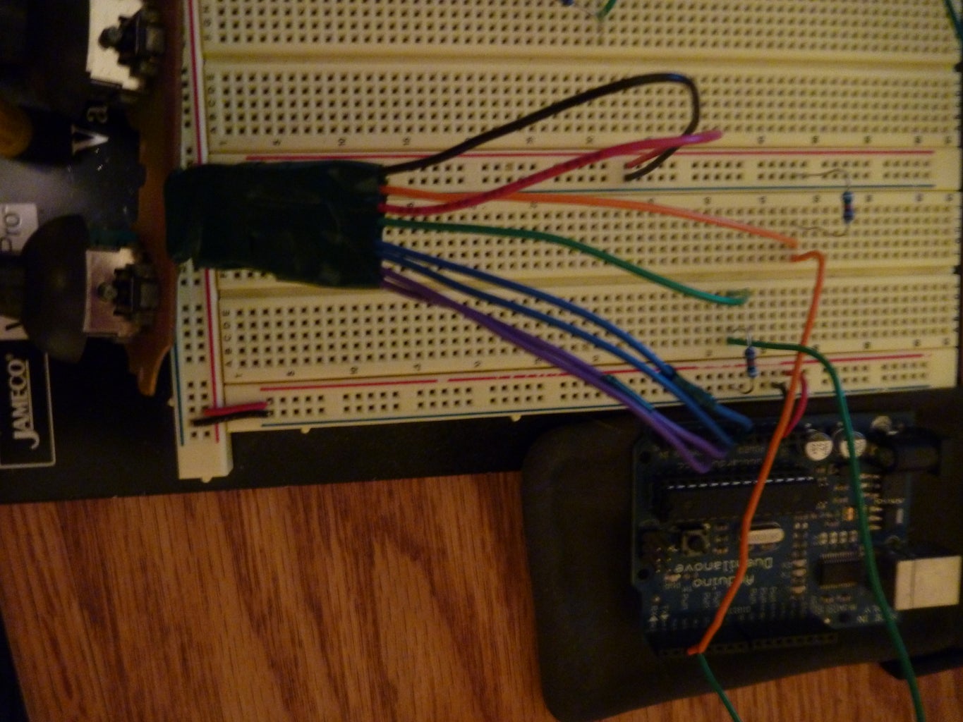

To connect the wires to the Arduino, connect Vcc and GND like anything else, connect all four of the thumbstick potentiometer wires to the analog pins of the Arduino, and connect each button wire to a simple button circuit (eg I have an orange wire from the controller, so I connect to a junction with a 9.5 kOhm resistor to ground, and another wire from the junction going to a digital pin of the Arduino).
If you need any help setting up the circuit, feel free to message me and I'll be glad to make a circuit diagram or set up my breadboard neatly so that it's easier to see what's going on.
Here's the demo video again for anyone who skipped it in the intro:
PS: leave some feedback! I'd love to hear from anyone!


