

Introduction: Flickering Lantern for Halloween


As I walked into the hardware store the other day my eye was caught by a large display of strobing lanterns. I was immediately drawn to them forgetting about why I was even in the store! After a bit of contemplation I thought that while they got my attention there were a number of things that could be improved:
- using an old kerosene lantern rather than a plastic replica
- using an RGB LED to provide a more interesting light than white
- using an ardunio to produce a flicker effect rather than a strobe
I would like to say the above was the reason to build this project, but let us be truthful, the main reason was so that I could have a bit of a muck around on a rainy day!
I do like the end result and it will be hanging over the front door this Halloween.
Step 1: Materials and Tools


I got the bulk of the components from ebay. The lantern came from a local second hand shop, it was cheap due to its condition but that is exactly how I want it!
The battery connection was based on the instructable by miceuz ( https://www.instructables.com/id/DIY-9-volt-battery-connector-for-free/) with the addition of a switch hotglued to the top of the connector. This is a great instructable and saved me when I didn't have a battery clip.
The step down convertor is used to go from 9V to 5V. I used an adjustable module but anything that steps down the voltage to the correct level will work.
Materials
- Kerosene lantern or similar
- Ardunio nano
- 470ohm resistor
- WS2812B 2*2 5050 RGB LED Lamp Panel
- Battery clip with switch
- DC-DC Buck step down convertor module
- Heat shrink (or insulation tape)
- Zip ties
- Bamboo skewers
Tools
- Soldering iron
- Multimeter
- Wire cutters
- Small screwdriver
Step 2: Set the Voltage Regulator Output

As I wanted to hang the lantern above the front door I need to use a battery as the power supply. A 9V battery is convenient but the voltage needs to be reduced to 5V to suit the LED. I used a buck converter rather than linear voltage converter as that is what I had in my parts bin but I do believe that they are more efficient anyway.
If you use an adjustable convertor like I did, you will need to tune the output prior to connecting it to the remainder of the circuit.
Connect the converter to the battery. Measure the output with a multimeter. Using a small screwdriver, adjust the output until 5V is measured.
Step 3: Connect the Components
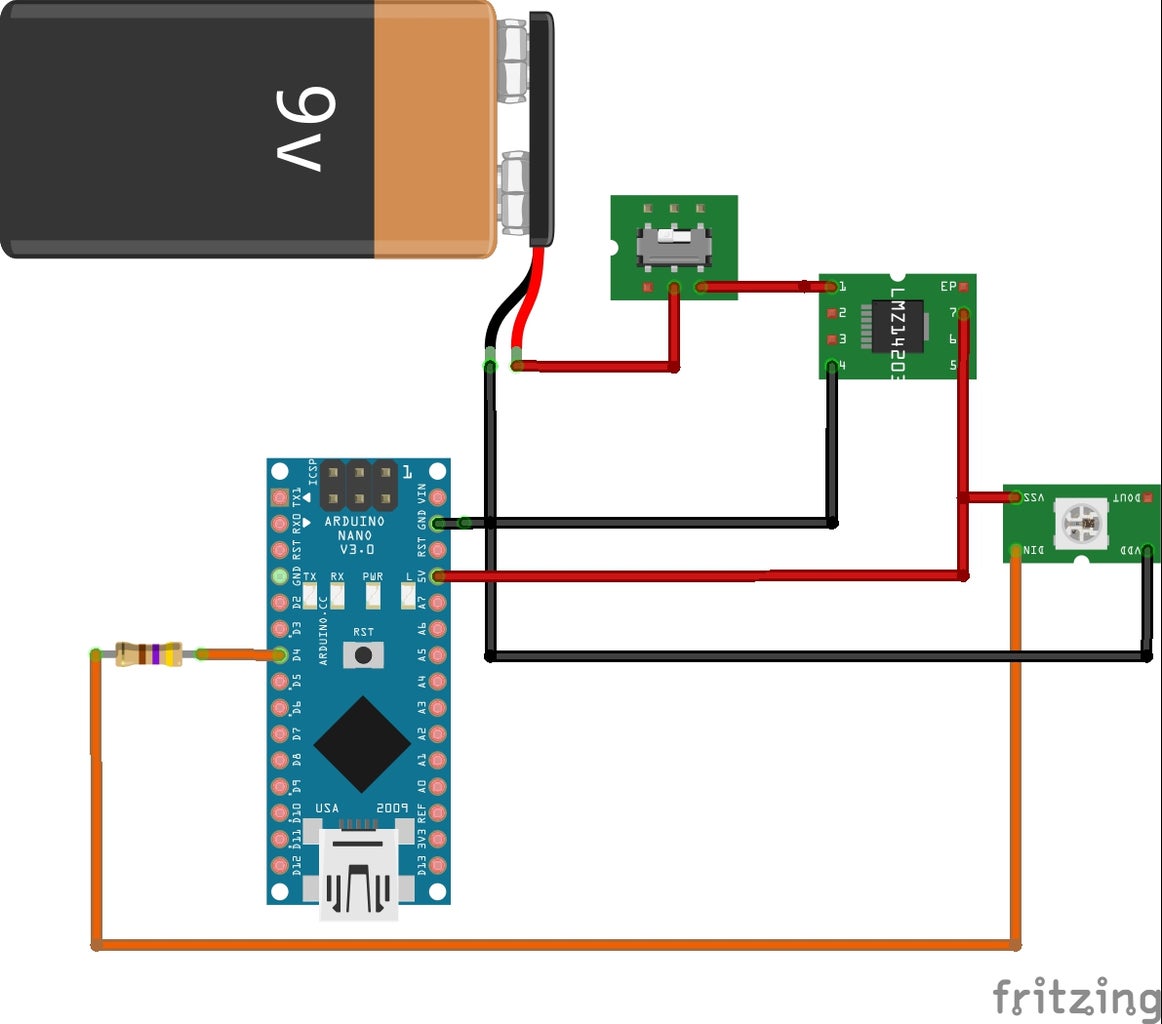

Connect the componts as shown in the picture. I was unable to find the correct image for the voltage converter but you get the idea! The battery lead is yet to be connected in the photo but this should be done at this time as well.
The LED control wire is connected to D4 of the Nano. Originally I connected and soldered the resistor to the nano and then the lead to the LED but this lead to difficulties in a later step. I finally connected it in line with the control wire, putting heat shrink on the joints.
All joints should be covered with heat shrink or insulation tape.
Step 4: Code
The flicker effect is generated by having the LED randomly dim in brightness. Originally I had it going to black but that created more of a strobe than a flicker.
With a bit of trial and error the best flicker effect was found when the LED was brighter longer than it was dim. This was achieved by setting the bright time with (random(500)) and low time with (random(200)) each time through the main loop.
I was in a little bit of a rush when I did this so used LEDS.setBrightness to change the illumination level. I think that a better effect might be achieved by changing the hue rather than the brightness. I will give this a try at some stage but keen to hear anyone elses' ideas on this.
Another thing to experiment with is the color of the LEDs. I used the predefined color "goldenrod" as it resembled a candle light but you might want to go to a red for that extra impact!
You may also note in the code that the LED was defined with "GRB". This is the order of LEDs in the module that I had. You may need to change this to RGB for your LEDs to show the correct colors.
Attachments

Step 5: Fit Electronics to the Lantern


I didn't want to permanently alter the lantern so was limited in how I could mount the components.
Start by removing the glass chimney to allow the LED to be fitted.
Pass the wires in through a top vent and bring the LED panel down to the required level. Cut a bamboo skewer to a length that allows for it to be jammed into place (see photo). A second skewer was then fitted across the first and the LED attached via a zip tie. Replace the chimney.
Put the nano and voltage regulator into the anti-static bags they came in to insulate them against the side of the lantern. Secure the battery and the bags with a zip tie.
This all looks a bit messy but when the lantern is hung up you can't see the back of the lantern. If you were going to locate the lantern in a position where the back would be seen you would need to hide the components a bit better. Remember it will be dark so a simple black bag maybe enough...
Step 6: Hang and Enjoy!
I hope you enjoy this simple lantern.
I think that there are a lot of modifications that could be done to improve this, tinker away!!!

Participated in the
Halloween Contest 2017


