

Introduction: Foolproof ESP8266-12E Programming and Use


If You Don't Want to Read this Whole Article, Here's the Jist:
- Solder 2mm male headers onto all your ESP8266-12E units as soon as you buy them,
- Remove the ESP8266-12E from one Adafruit Huzzah Feather board, and solder on two 8-position 2mm female header sockets and use the Huzzah Feather as a programmer,
- Make a DIL-16 to ESP8266-12E adapter so you can do prototyping on a standard breadboard,
- Include 2mm female socket headers on all your projects so you can plug in one of your programmed ESP8266-12E units.
OK, More Details
Ever since the ESP8266 in all its variations came upon the market, lots of people including me have been fascinated and excited to use it in projects.
At first, the way you would use the ESP8266 was either to program it with its native language and tools, or use it as a "modem" using the old AT modem commands that are literally decades old. Then, the Arduino community made it possible to use the ESP8266 directly as an Arduino! With the hard work of the community, we are now able to program the ESP8266 right in the Arduino development IDE. (There are lots of Instructables and pages on the web about how to program the ESP8266 right in the Arduino IDE, so I won't duplicate that here.)
Unfortunately, soon after most people try to program and use the EP8266 in a project for the first time, they find out that it has a lot of pitfalls, such as the need to use a USB to serial adapter like an FTDI or similar unit with the associated drivers and security issues to overcome. People also discover that they need to attach the electrical connections to the programmer and then to the circuit, and they need to connect certain pins in just the right way before the ESP8266 can be programmed or made to run. It is very frustrating to say the least.
I have a huge number of projects that I want to use the ESP8266-12E for, but I was being stymied by these issues. So a few months ago, I tackled the problem head-on and have come up with one path that provides foolproof way to:
- Connect the ESP8266-12E to a programming circuit
- Program it from within the Arduino IDE
- Connect it to a breadboard for prototyping
- Connect it to your final circuit
- Use the ESP8266-12E reliably!
I think once you try this, you will decide to use this technique with all of your work with the awesome ESP8266-12E.
Step 1: Connecting the ESP8266-12E

How Do I Connect This To My Stuff?
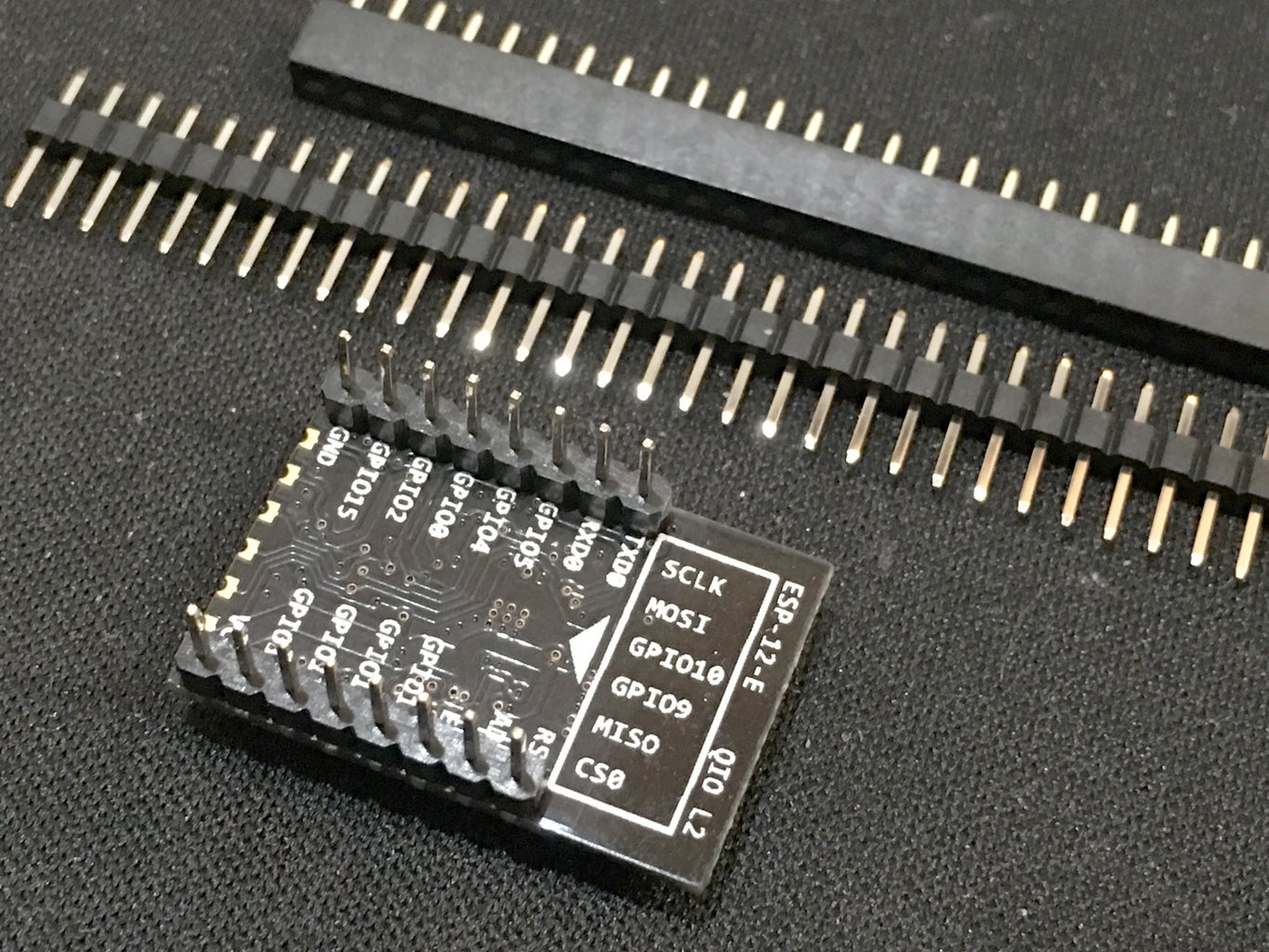
One of the obstacles people encounter early on with using the ESP8266-12E is that it has only pads, but not any sort of pins, and the pads have a 2 mm spacing pitch. Most breadboards have a pin spacing that is 0.1 inch, which makes it impossible to plug the ESP8266-12E into a breadboard without an adapter.
My solution is to purchase 2 mm male and female headers and solder the male headers to the ESP8266-12E. Then in each circuit (and on the programmer which we will discuss on the next page), you can simply plug the ESP8266-12E into your circuit, and replace it if needed. I found that Adafruit had the best pricing on these headers, so I purchased them there. Here's the ones I selected:
2mm Male Headers:
https://www.adafruit.com/product/2671
2mm Female Headers:
https://www.adafruit.com/products/2672
Then I just soldered them to the ESP8266-12E. The pads are small, but most people should be able to solder these without any trouble.
What About Using a Socket instead of Header Pins?
For a while, I was experimenting with 3D printed sockets that I saw on Thingiverse (like this one: http://www.thingiverse.com/thing:1670366), and I even designed a few of my own, but the wire legs proved to be very difficult to get right so the ESP8266-12E would snap into place and stay connected. I think a great project for someone to do on Kickstarter or Indigogo would be to design and manufacture a PLCC-style socket for the ESP8266-12E. If you want to explore this, contact me! I do have a prototype that works that we could use as a starting point.
I also played around with a design for the programmer that used pogo pins soldered to the pads on the Huzzah Feather, with a 3D printed case. Pogo pins are really cool if you haven't checked them out. It worked really well, but when I couldn't get the socket to work as well as I wanted, I decided to just go with header pins for everything. That's when I modified the Huzzah board to have female header sockets to accept the ESP8266-12E.
Step 2: Programming the ESP8266-12E


How Do I Connect the ESP8266-12E To My Computer's USB Port?
Normally, to program the ESP8266-12E, you have to connect certain pins to each other, and to ground and VCC, and a few of the GPIO pins need to be connected correctly. You then connect the TX and RX pins to your USB-to-serial adapter like the FTDI or CP2102 or similar boards. Finally, you have to reset the unit with pins connected in specific way to put it in programming mode. It is really a pain I think.
Too Many Problems!
In my experience, sometimes this all would work, and sometimes it would not work. But usually, trying to program the ESP8266-12E would result in the dreaded message from the Arduino IDE saying "Warning: espcomm_sync failed" or "Error: espcomm_open failed". Argh!!!
Solutions were always different, and included restarting the computer, trying another ESP8266-12E while the original one "rested", switching between FTDI and CP2102 adapters, reinstalling drivers, tricking the security in the OS to allow access to the USB port, and all sorts of other illogical voodoo steps.
Trying Out Dev Boards Instead of Bare ESP8266-12E Modules
Out of frustration, I purchased a variety of dev boards such as the NodeMCU, the Sparkfun "Thing", and the Adafruit Huzzah Feather. These boards all have an ESP8266-12E, but also provide all the support circuitry to supposedly make it easy to program and use the ESP8266-12E. Supposedly, you are able to just plug it into your computer with a USB cable and program it.
Still No Good!
I ran into problems with both the NodeMCU cards and the Sparkfun Thing cards. The problem was with the drivers for the USB-to-serial part of the board. Like using the discrete FTDI and CP2102 USB-to-serial adapter boards, the drivers just would not allow me to connect reliably to the board when I was in the Arduino IDE. Sometimes it would work, and most times would give me an error when I tried to program the board.
A Step Closer to the Solution -- Adafruit Huzzah Feather
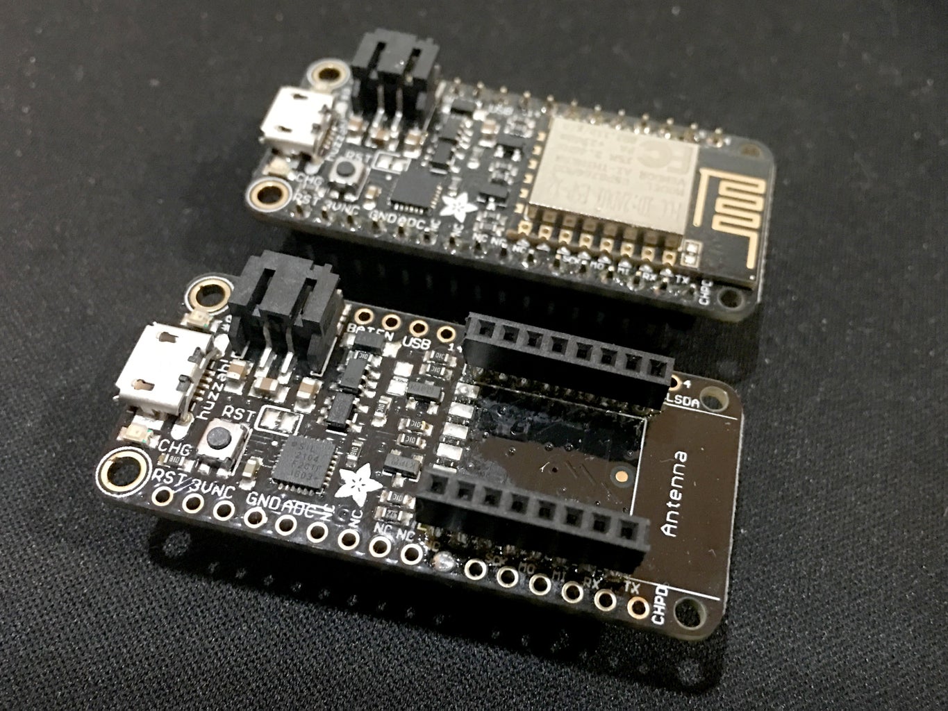
Finally, I tried the Adafruit Huzzah Feather. I found that it did not seem to use the same drivers as the other boards for the USB-to-serial circuitry, and programmed the first time right away. In fact, as I programmed it more and more, it never failed!
The problem is that even though the Huzzah Feather is a really awesome card and even includes a connector for a lithium polymer battery pack for power and charging, the card is $15. That's not bad, but part of the excitement about the ESP8266-12E is that you can buy them for around $2 each! I wouldn't personally want to embed a $15 board in a typical IoT project.
The Huzzah Feather has an actual ESP8266-12E SMD soldered right onto its board! This gave me an idea.
Using the Huzzah Feather as a Programmer
In my tests above, I purchased two Huzzah Feather units from Adafruit. You can find the link to buy one here: https://www.adafruit.com/product/2821 Unfortunate, as of today (1/6/2017), the product is indicated as "out of stock". Hopefully this is temporary.
I unsoldered the ESP8266-12E from the Huzzah Feather board (I destroyed it in the process because the solder that is used on the ESP8266-12E seemed to have a lower melting temperature than the solder used to bond the ESP8266-12E board to the Huzzah Feather board, so when I used a hot air rework gun to loosen the ESP8266-12E, all of its components came unsoldered and fell off!). Then I cleaned up the 16 pads on the Huzzah Feather board, and then soldered two 8-position 2 mm female headers to the pads. This allows me to simply plug any ESP8266-12E which is equipped with male 2 mm header pins right on to the Huzzah Feather board and program it. Then I can unplug it and plug it into my project circuit which also has the two 8-position female 2 mm header sockets.
Step 3: Prototyping With the ESP8266-12E


Now That I Programmed It, How Do I Connect This ESP8266-12E To My Breadboard?
Of course, one of the frustrations is connecting the ESP8266-12E to a breadboard for prototyping.
The issue is that the pitch of the header holes on the ESP8266-12E is 2 mm, not the 0.1 inch spacing that breadboards usually have.
There are lots of breakout boards available to adapt the ESP8266-12E to standard breadboard spacing, but they typically take up most or all the pins in the rows of the breadboard, rendering it fairly useless.
I designed the adapter board below, which has a few key features:
- Uses a DIL-16 pattern to connect to the breadboard, which leaves as many holes as possible left available on the breadboard.
- The ESP8266-12E rests off to the side of the breadboard.
- The adapter uses female 2 mm header sockets to allow you to plug in your ESP8266-12E after you program it with the Huzzah Feather.
- The adapter is a single-sized PCB board, so it is fairly easy to make at home. I used an OtherMill to make mine.
For my adapter, I chose to not include the connections and components that the ESP8266-12E typically needs when you use it in an actual circuit so that I could include those connections and components in my breadboarded prototype, and then include them in my final circuit.
Step 4: Using the ESP8266-12E in the Final Project
Whenever I create a circuit board which will utilize an ESP8266-12E, I simply solder on two 8-position female 2 mm headers. This allows me to plug the programmed ESP8266-12E into my project, and swap it out as needed.
Step 5: Conclusion on Using the ESP8266-12E
I have described here how I have decided to tackle the ESP8266-12E to make connection, programming, and use of the ESP8266-12E painless and trouble-free.
When I Buy New ESP8266-12E Units, I Add Pins and Program Them with Blink
Now whenever I purchase a sack of ESP8266-12E units from eBay or other suppliers, the first thing I do is solder male header pins into the holes along the sides. Then I plug it right into the Huzzah Feather board on which I previously removed the ESP8266-12E and soldered on two 8-position female headers, and I program the Blink sketch to it to test.
Now I have bags of these ESP8266-12E units with pins already installed and tested so I know they can be programmed.
Whenever you look at any of my finished ESP8266-12E projects, you'll see that the ESP8266-12E can easily be unplugged for programming or replacement. It looks professional, is robust, and no longer do I have to worry about connecting, programming, or deploying the lovable ESP8266-12E.
What's With the Number Stickers?
You may have noticed the small stickers on my ESP8266-12E units. What are those numbers you might be asking? Well, each ESP8266-12E has a serial number or ChipID which is actually the original MAC address when the unit left the factory. I'm not sure if the numbers are guaranteed to be unique or not, so I'm not sure if the number is reliable. However, when I solder the pins onto a new ESP8266-12E unit and I plug it into the Huzzah Feather unit to program it, I program it with a version of the Blink program that also echoes the internal serial number to the Serial Monitor. I use a little program to make a list of all the numbers of the bag of new ESP8266-12E units, and then print out stickers and put them on the shielding can of each one. I do this because some of my projects require me to know the number when I'm in the field.


