Introduction: Four Port USB Hub
This is a four port USB 1.1 hub built on a tweety bird theme.
Step 1: Getting the Components Together
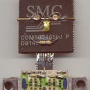
First, the USB hub controller. Texas Instruments make, among others, one four port USB 1.1 hub in a 32 pin Quad package. They call it the TUSB2046. That is the black square at bottom right, in the picture.
It needs a regulated power supply of 3.3 volts, supplied by a three terminal low dropout regulator. Microchip make one, called the MCP1700T-3302E/TT though the actual chip is a tiny thing. Look carefully, you might just be able to identify it.
The other components were salvaged from various sources. The 6 MHz Crystal came from a Television set, where it was clocking the remote control microcontroller. The capacitors and resistors were unsoldered from various boards from junked equipment.
Step 2: The Circuit Board
The circuit board was partly etched, and the rest of the pattern hand carved using a hobby knife. No computer was used in any part of the production of the circuit board.
The only contact the circuit board had with any modern electronics was when it was photographed so that its picture could be displayed in this web site.
A piece of copper clad board was cleaned, and covered with etch resist ( I used a permanent marker pen ) and the integrated circuit clamped over it with alligator clips.
A needle was used to score fine lines where the copper was to be etched away, the ic removed, and the pattern finalised.
Then the board was made the anode in a tank filled with common salt solution with a straightened paper clip anode, and current passed till the pattern was completely etched.
This process, I feel, needs its own instructable and this I might do if wheedled / threatend / cajoled / asked / whatever works.
Step 3: Soldering the Components - 1
First, the power supply.
The three terminal regulator whose name is longer than the device itself, that microchip wonder, was soldered in together with the two capacitors needed on its input and output.
I took the opportunity to solder some other bits and pieces too.
A piece hacked off an old ISA board became the USB connector. Wires of the proper colour were selected for connecting it - black for the negative, red for positive, and white and green for the USB data lines.
After the voltage regulator was fixed on board, it was time to test it, which was the next step.
Step 4: Testing the Work So Far - 1
The diagram shows the circuit on the board so far. The voltage regulator was tested by applying five volts to it (from the USB port of my computer) and verifying that the output was indeed at 3.3 volts.
Then a 15 ohm resistor was held to its output terminals, thus imposing a load of about 220 milliamperes, and the voltage was still verified to stay at 3.3 volts - at least, until that resistor had gotten too hot to hold. Microchip says that their chip will supply 250 mA and since Texas Instruments say their chip will draw a maximum of 40 mA I think the two of them will just get along fine.
The rest of those bits and pieces were also tested to make sure that the act of soldering them had not caused them to give up the ghost.
Step 5: Solering the Components - 2
Some more components are soldered in, and then I reach for my multimeter.
On a project of this type, where you are working on a design for the first time, it is essential to take frequent breaks and check the work.
You check the components you just soldered in, then you check the components you had already tested - just in case the action of soldering in the fresh components had not caused the old ones to give up the ghost.
I have added ferrite beads on the incoming supply lines, and the 3.3 V supply line from the regulator to the chip.
Step 6: Soldering the Components - 3
I solder some more components in.
These are the one resistor and two capacitors around the quartz crystal. Since the crystal is a large thing and I tend to drop the board a lot, it will be put in last of all.
Step 7: Soldering the Components - 4
I solder in the transient suppressor diodes.
I had a few dual diodes in a Small Outline Transistor package - SOT23 - lying around, and still in place on a junked telecommunication circuit board. This project seemed a great place to give them a second lease of active life.
Step 8: Soldering the Components - 6
Some more components in. I have cut the islands for the USB downstream ports, eight of them for the two datalines each.
Fine enamelled wires have been soldered to the controller data lines to route over to the series resistors and surge suppressors.
Using fine enamelled wire gives you great packing density over etched lines on board, especially on a single sided layout like this.
Step 9: Soldering the Components - 7
I tidied up the data lines from the chip to the surge suppressors via resistors.
The texas instruments datasheet says the chip needs 27 ohm resistors in series with all its data lines - all ten of them (eight downstream, two upstream). I could find only 22 ohm resistors in the various junked boards I could collect, so they would have to do.
The pads of the chip were tinned in preparation of soldering it in position.
Step 10: Soldering the Components - 8
There - I have soldered the crystal in, and now only the chip is left.
So now I know that every component has been connected up correctly, and is functionally all right, because I have been testing them after each operation and rectifying any defects I found.
Now is the time for a quick check. Connect it to the computer and see what it has to say.
Since the USB hub controller is not in yet, it will have to report a fault. I want to see that fault message.
Step 11: The Error Message in Case It Doesn't Work
This was the reaction of windows xp to the chipless controller. One data line is pulled up to +3.3 V through a 1.5K resistor and this tells the computer there is a fresh device on the bus.
However, its queries elicit no response so it decides that a faulty device has been plugged in.
Great. Now we know what to expect if we goof up.
Step 12: It Works!
After the chip was soldered in and the device plugged in, the "new hardware found message" was replaced by the "device is installed and ready to use" message balloon.
Step 13: The Final Board So Far
This the work done so far. The upstream port connection is done, but the four downstream ports have to be connected.
And a wav player that says "I taw a puddy tat" is in the works, and it will be built into a pedestal below the tweety pencil holder in the first picture.
Step 14: Generic Hub
Windows XP has recognized my handiwork as a "Generic USB Hub". I just obtained the chip from Texas Instruments and followed the circuit on their datasheet.
So the credit should really be awarded to them.


