

Introduction: Fritzing: an Introduction


When creating a project or circuitry you usually need to draw out a schematic of the circuit before you start. Drawing a circuit is very helpful but it might not be as to scale as you think. The program known as Fritzing is an open source hardware initiative that allows you to create and plan circuits out before creating them. The program comes with a bunch of pre-loaded circuit boards from different companies such as Arduino and Sparkfun. You can use these boards to plan out your project pretty accurately because they are made to be the actual size of the physical board.
This Instructable was made to help look at the general process of the Fritzing program and provide some tips and tricks.
Step 1: Creating a New Circuit
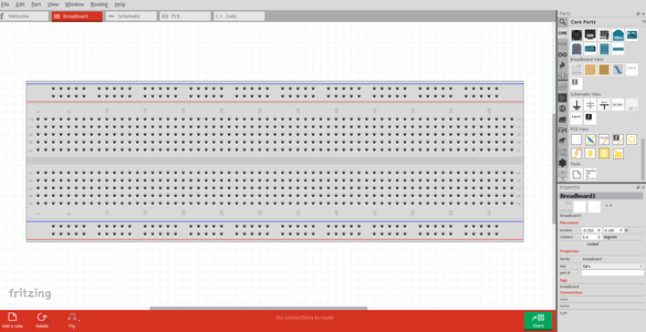
When you start the Fritzing program you will prompted with a welcome screen. This screen contains news, your recent files, and some tips of the day. From here you can select the Breadboard window to start a new circuit. There will be a blank breadboard already in place. You can either build off of this board or you can delete it. This is the main work area. If you choose you can also build your circuit in the Schematic view or the Printable Circuit Board (PCB) view.
Step 2: Adding Components


Adding new components is pretty simple. There will be a window on the right side of the screen with parts. Simply go click on one of them and drag into the window you are working in. When you click on the component the program will show information about the size, resistance or the purpose of the part. You can also rotate the part by using Crtl+R. If you need to find a specific part but not sure where to look there is a handy search bar that will find what you are looking for.
There are other sections of the parts window that will lead to specific company’s products. You can also upload any boards or parts you have created or downloaded. If you go to the Mine section of the parts window and right click you can import any parts.
Step 3: Wiring Components


Once you have the components you will want to wire them together. By clicking on one lead of the component you can drag and start creating a wire. Drag the wire to the other pin you want to connect together and it will click to it.
If you are creating a large circuit with a lot of wires you can create bends in wires to change the path they take. Just by clicking on the segment of the wire you want to bend will create a bend point. You can manipulate this as much as you want. Another tip for working with a lot of wires is setting the wires to be curvy. If you go into the Edit drop down window and go to preferences. A window will open and if you click on the breadboard view you can have a curvy wire setting activated. This will allow you to bend wires in a unique fashion. You can also create bend points still by holding down Ctrl and clicking.
Step 4: Schematic View


One of the cool features of Fritzing is the ability to see the circuit you’ve made in the breadboard view in a schematic version. The wires might be tangled when you first get in the schematic section but you can still manipulate the parts and wires however you want.
The schematic view is great for making sure your circuit is set up correctly. It will be a handy tool to use if you want to do some circuit analysis.
Step 5: PCB View

Another view is the printable circuit board view. In this view you can see how your circuit would look if you were going to have a FAD print it. You can still manipulate the parts and wires just like in the other views. The best part about this section is you can actually send your design in to get it printed. The Fritzing website will give you the correct steps for ordering your PCB.
Step 6: Coding

If you are using a programmable board for you design the Fritzing program will let you code with it. You have to select the platform you are working with and the correct board you are using. Type out the code you want to upload to the board and hit upload.
Step 7: Creating Your Own Parts


If you ever wanted to create your own boards or parts for Fritzing you can! All you need to do is create the part or board you want in a program such as Adobe Illustrator or Inkscape and save it as a .SVG file. You will need to create each of three views for your part. There are many tutorials about creating your own parts. Check out some of them before making your own. You’ll need to keep track of your layers as Fritzing has specific layers need for certain views.
Once your svg file is created you can drag any part such as an IC chip and the click on the “edit this part option.” A window will open and you can up load all the images to the perspective tabs. You’ll want to edit the Meta data part that way you can add your own description to the part. You can also change the number of pins on the board and rename the pins as you see fit.
The tedious part of creating a circuit is selecting each pin on the image you created. You will have to click on each pin and then select the part of the graphic you want to be that pins hole. This can be a lengthy process if you have a large number of pins. You will need to do this for each image you upload. Make sure to save your project frequently.
Step 8: Wrapping It Up
While Fritzing can't simulate the circuits you've made it is still a great tool to use when creating a project. It can help you plan ahead and see how big you project will be. You will be able to see how many resource you will need to get. It is a great planning tool and will help when trouble shooting a circuit because you can easily access your schematics.


