

Introduction: Fume Blower


This is a soldering fume blower/extractor project.
I used to use a simple PC fan to blow away harmful fumes while I was soldering, and always planned to make a solid fume extractor tool - but never seen the concept I really want to realize. Until I found lor123's design here at instructables.com. This project is a remake with some modifications.
Note: If you need a fume extractor rather than a blower, then you should follow the link to lor123's instuctable.
Step 1: Features

First of all, I usually make my soldering jobs on my balcony at free air, so what I need is not a fume extractor with replacable (and costly) active carbon filters, but an air blower to get the fumes away from my face while soldering.
With a fan placed on the workbench it is a real problem to focus the beam of the air flow to the soldering point. I used to have different items at hand to place under the fan, trying to get the air flow right to the tip of the soldering iron. This was so annoying that I often skip the process, and breath some harmful fumes... (Shame on me, I know.)
With the flexible stam of this fume blower redirecting the air flow is a matter of a moment. Also, it is an important feature to be able to fix the thing onto any table with ease, while it does not use up any surface of the table, as it is clipable to the side of the desk.
I love the idea of the integrated LED lights on the front of the fan. As it is pretty close to the work item you just working on, a direct spot light is a very nice thing to have. LEDs does this job very well.
A DC connector and a simple ON/OFF switch is integrated into the lamp's house. I like to use solar power as much as I can. This fan is powered from 12V solar battery bank (as well as my soldering station, DC power supply unit and more), or from a 10V DC wall transformator.
Step 2: Parts and Tools


This fume blower/extractor is made from a low cost, clipable, flexible-stam lamp (obtained from Ikea).
Other parts are:
- 12V DC fan (probably from an old PC)
- grid to the fan
- one or more LEDs (I used 12k lumen jumbo LEDs for this project, but any high intensity LED will do)
- 230 Ω resistor
- 4.7V Zener diode
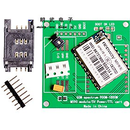
- a small piece of prototype board
- DC connector
- switch
- a piece of wire
- screws
- metal strip or other material to fix the fan to the lamp
Required tools:
- drill
- soldering iron
- screw driver
Step 3: Assembling the Parts


Instructables.com is not just about ideas, but instructions too. So I made for you a brief summary of steps I performed to get the product ready.
- After succesfully prototyped the circuit on a breadboard, I arranged the LEDs, the resistor and the diode on the prototype board, until I get satisfied with the layout.
- Then disassemled the parts, and cut the prototype board to the smallest size that can accomodate all the required parts.
- Did the soldering work, including two small wires which will provide power to the circuit.
- Then I used a double sided adhesive tape to fix the board with the LEDs to the grid of the fan.
- Then partly removed the sticker from the fan to get to the wire's connection points, and soldered my short wires to them, taking care of polarity.
- I drilled appropriate holes into the house of the lamp for the DC connector and the switch.
- With a short wire I connected the DC socket to the switch.
- One of the wires of the fan was soldered to the DC connector's other terminal, while the other wire of the fan was soldered to the switch.
- Then the DC connector and the switch was fixed into the lamp.
- The final step was the fixation of the fan to the lamp. I considered the use of hot glue, but finally decided to use some metal strip and screws. Not beautyful, but solid and permanent solution.
- Finally I found that the fan with the metal grille on it is too heavy for the flexible stam of the lamp. As a quick and easy solution I covered it with duct tape to borrow some steadiness to the stam.
Step 4: Schematic

This is a simple circuit. The only swirl here is the use of a Zener diode. The role of this part is to provide a fix voltage to the LEDs, regardless of the input power. As I power this tool from a 12V solar system (which actually operates on 12.5-13.5 Volts), a 10V wall transformator, and sometimes from a 9V battery, the LEDs should have the same voltage. The serial resistor is set according to the 4.7V provided by the Zener diode, and ensures a fixed current flow to the LEDs.
A Zener diode can handle relatively little current before it getting burned out by the heat. So I made some calculations to see if I can safely drive my two LEDs with a small Zener diode. I would give 10mA to each LED, so I've chosen a 230 Ohm resistor to feed them with 20mA total. (4.7V / 230 Ohm = 20mA)
LEDs are usually rated to operate with 20mA current flow at max, but they are almost as bright on 10mA to 15 mA as on 20mA, while the lower current rate gives much longer life span to the LEDs. So as a best practice I made sure to set amperage below 20mA per LED.
If you plan to use this tool with the same voltage every time, e.g. you use a 9V battery as a power source, than you can safely omit the use of Zener diode. Don't forget to change the value of the resistor, though:
- For a fixed 9V input you should use a resistor between 470Ω to 220Ω
- For a fixed 12V input you should use a resistor bethween 620Ω to 300Ω
The higher value gives 10mA current to the two LEDs, the lower value brightens them with 20mA.
(Note: the schematic above was made by the free TinyCAD software.)
Step 5: Final Words


The direction of the fan determines if it blows or sucks the fumes.
The light is focused, but with diffused LEDs (or making them diffused with sandpaper) you can get fine, not that harsh lights.
Fan speed control is not neccessary, as the fan is quiet below 12V.
Also a flywheel diode is not neccessary for two reasons:
- The Zener diode is protecting the LEDs from the voltage spikes generated by the fan when the power source switched off.
- With such a little motor the LEDs would not suffer any harm even without the Zener protection.
(A flywheel diode is used to conduct the energy stored in an inductor - in this case, the motor of the fan - to some useful end, or just to dissipate it. Without the diode the inductor voltage would spike up, which is a waste of energy and theoretically could damage components.)


