

Introduction: GPS Data Logger


While this is not the first Arduino based GPS Data Logger out there, it may be the most versatile. This device has a lot of features & even more possible uses.
It started with significant inspiration from Mikal Hart's "Reverse Geocache"TM and the use of his TinyGPS library. Jeremy Blum's Tutorials also helped us on some functionality & code improvement. Finally, we owe our small format & super portability to Rion's compact design.
We call the product "Location Based Entertainment" because of it's many usages, all based on providing entertainment based on your location:
The same device can be:
- An Inverse geocache
- A Data-Logging Geo-Guide
- Half a Twin
- Teenage Car Tracker
- Tourguide
- etc
As a Data Logging Geo Guide, this device of course displays & records your location every time you push the button, but also records what date/time it is & how far you are from your destination along with the sequence number. Once at your final destination, it will activate it's wireless adapter & transmit the whole content of the SD card to the Base station so your journey can be plotted on Google Earth.
Please refer to inversegeocache.tumblr.com so see more pictures & descriptions and goto www.stgeotronics.com to order components, kits or assembled/tested finished products.
Step 1: PCB Design


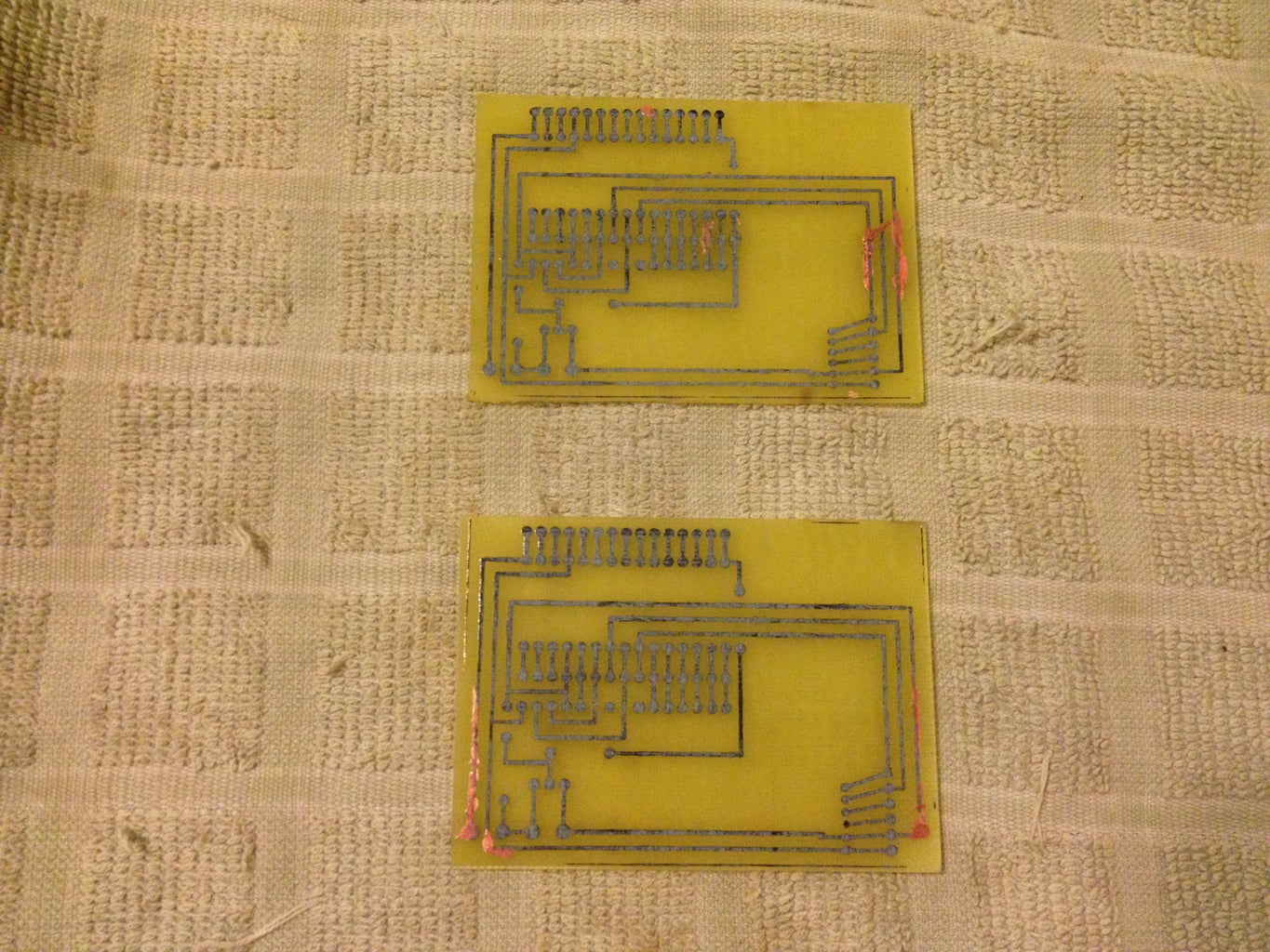


We started with a Breadboard prototype, then quickly generated our first PCB in the garage. Right from the start we knew we liked the Arduino Nano for its miniature format.
Watch "Sylvia's Super-Awesome Maker Show!" for an excellent tutorial on how to easily produce your own PCB.
http://sylviashow.com/episodes/s2/e4/mini/etching
The first PCB only had the nano, a 16x2 LCD & a GPS, so it was single sided.
We very quickly realized we should add an RF24 Wireless transmitter on board and why not an SD card. Second generation PCB was born and was double sided.
Once we added the Mosfet & OptoCoupler to power it off via software, we knew we had a complete PCB.
Time to get the PCB "Fab"ricated.
Step 2: Gather the Components

Regardless of whether you print your own PCB or order it on-line, next step is to acquire all the parts you'll need:
Parts List
___________
1- LBE PCB Pro/Mini or Nano)
1- Arduino Pro/Mini or Nano
1- Parallel LCD 16x2 or 20x4
1- SKM53 GPS
1- SD Card Reader/Writer
1- nRF24L01+ Board
1- Mosfet
1- Opto-Coupler
1- 100 Ohms Resistor
1- 470 Ohms Resistor
1- On/Off Switch
1- N/O Pushbutton
Pinout Specs
____________
LCD: (2, 3, A0, A1, A2, A4) 5 is Vo pin
GPS: (4,6)
SD: chipSelect = 7
RF: cePin = 9, csnPin = 10
Mosfet: power = 8
Step 3: Device Assembly


Here is our step by step assembly guide.
We love the Pelican 1015 cases as they are waterproof & provide just the right amount of space for all components while providing a very small footprint.
1. Solder Arduino Pro/Mini (or Nano) pins on back side of PCB (S&T in upper right corner). Don’t forget the 2 little pro/mini pins that go between the 2 rows: A string of 12 pins on one side, a string of 12 with the 5th pin missing on the other side with the 2 isolated pins behind this gap.
2. Solder the 2 groups of 6 pins on front side of PCB for the LCD. DO NOT solder LCD yet.
3. Solder SD card reader/writer on back side of PCB after applying double sided tape to the SD Card Reader.
4. Solder Pro/Mini (or Nano) on back side
5. Solder LCD on front side after applying 2 layers of double sided tape to the back of the LCD.
6. Test assembly by transferring & running the LBE Sketch on the Arduino with power through USB cable connected to laptop. Troubleshoot if Display or SD card errors. It is normal for the display to have a little flicker from USB Power. 9-Volt battery will later correct this.
7. Solder Resistors. R1 = 100 Ohms, R2 = 470 Ohms.
8. Solder Opto-Coupler on front side
9. Solder Mosfet on front side on top of opto-coupler after bending Mosfet pins backwards and putting double sided tape on opto-coupler
10. Solder RF24 on front side
11. Solder GPS on front side
12. Solder Push Button
13. Solder On/Off switch interrupting either one of the 9 Volt connectors, as shown below. Solder resulting assembly to board, making sure to respect polarity.
14. After moving all the libraries to their required location on your computer & the Sketch to your desired location, insert SD card in SD Reader/Writer slot.
15. Test Assembly (you may have to go outside to get a GPS fix).
If using a Pelican 1015 case, drill a 1/8” hole on top right side towards back for pushbutton & 1 1/16” hole on top right side towards front for on/off switch. Insert/screw switch & button in place. Then, simply squeeze assembly in center of case & you are ready to go! 9 Volt battery should fit just fine on left side of PCB (if using a Pelican 1015 case).
Congratulations, you are done. Enjoy!
Step 4: Software

This is where this device shines the most.
With all the components tightly integrated on this compact PCB, with room for expansion, it's all about the software!
Our latest use is a complex 11 Stage Geocaching hunt where we only tell the user how far he is from the target after we deliver a compelling story plot. Of course, everytime the user turns the device on, we log date, time, location and distance to target. When he arrives in range with base station, the device will automatically transfer all this data wirelessly to a Google Earth connected laptop to display the user's path.
Being Open Source means all sketches are available.
We can't wait for the community to show us what other use(s) you come up with...

Participated in the
123D Circuits Contest

Participated in the
Supercharged Contest


