

Introduction: Generator Governor

This is a summary of my Arduino project to replace the faulty, mechanical governor on a home generator with an electronic version. This may not be the classic "how to" article but should have good information on parameter detection, evaluation and control. This could also be an engine governor since a generator is just an engine coupled to an alternator (AC power generation machine) in this case.
Some background, I live in a large suburban sprawl of the US east coast. Although the electric power grid in the area is excellent our immediate neighborhood has issues. It has become a question of not whether the power will go out but how long until it is restored. As a result I installed a home generator system.
The generator is a Briggs and Stratton 12kw standby generator. It has a Vanguard series V-twin engine displacing 627cc or 38 cubic inches and is connected to the home's natural gas (NG) supply. The alternator is set for 60 Hz (or 3600 RPM from the engine) and 240 VAC. An electronic control module (CM) in the generator senses utility voltage loss to start the generator. CM monitors oil pressure, oil temperature and faults, i.e. under/over voltage, under/over RPM, no start, battery charge fault etc. and will shutdown the generator should a problem arise. The CM has nothing to do with RPM governing.
The generator purchased used but in very good condition. It worked well for several years but began to have an RPM governing problem. RPM would hunt or over speed resulting in a shutdown. RPM oscillation or hunting in a generator causes voltage fluctuations as the voltage regulator can only react so quickly. The Vanguard engine uses a mechanical governor with flyweights but it is in the engine block and difficult to work on. Outside the block is a dual spring tension arm system connected to the carburetor throttle linkage. After some troubleshooting, the governor springs were replaced with a simple throttle linkage to control RPM. The engine ran fine when using a fix linkage. A professional wanted over $1000 to repair the governor which was too much for a 10 year old generator. Thus began the process to replace the mechanical governor.
WARNING: Read carefully before conducting a project of this type.
Do not to attempt unless you are very familiar with 240 VAC power, a natural gas fueled engine or moving machinery. If you are not comfortable working with any of these items or how to protect yourself from the dangers please do not attempt!!!
Step 1: Governor Basics


There are three types of governors in the small engine market; pneumatic, mechanical and electronic. Small engines are lawnmowers, pressure washers etc., with engines in the 100 cc-1000 cc size. Lawnmowers may have a lever to control engine speed manually or a pneumatic governor for constant RPM. A pneumatic governor usually has a vane that gets pushed by the air from cooling blower (attached to the flywheel). The vane has a carburetor throttle linkage and a spring to set tension which governs RPM. Mechanical flyweight governors are very reliable but difficult to repair once they do break since they are usually in the engine block. Finally, electronic governors read RPM, make some calculation and actuate the throttle. These are usually only on more expensive engines. An electronic device had the advantage of mounting components external to the engine and not have to take too much apart.
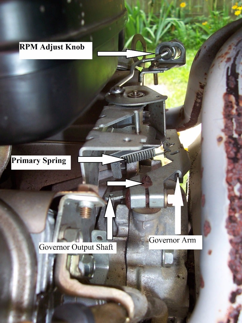
The pictures are a view of the engine and the throttle linkage and carburetor. The flyweights (not in picture) turn the governor output shaft which moves the governor arm. The arm movement and forces are balanced by the primary and secondary spring. When running, an increase in engine RPM will move the throttle linkage which begins to close the butterfly valve thus reducing air and fuel intake. In normal operation the governor arm moves very little and mostly due to changes in load meaning turning items on or off in the house.
Step 2: Actuator Type

A project of this type will take a great deal of research. DIY electronics have many websites containing a vast amount of information. Raspberry Pi and Arduino seemed to have the most information and support available. I had previously built my lawn sprinkler controller using Raspberry Pi and rszimm's Sprinkler Pi software so thought about going this route. One comment on Arduino forums defined everything. One of the moderators replied to a similar inquiry on what hardware to use saying Arduino was very good at doing simple tasks very fast. That was exactly what was needed.
I also had some exposure to stepper motors in college so this seemed the next choice to control the throttle. Again the forums had a great deal of information on similar projects. I was not as familiar with DC linear or rotary actuators so I decided to stay with steppers.
Space is limited so the actuator would have to fit in a tight space and be heat tolerant since it is in the engine compartment. After some research it looked like a NEMA 17 stepper motor would fit. A fit check using a NEMA 17 bracket, as seen in the picture, was the initial check. Based on NEMA dimensions, the stepper would fit also. Notice the throttle linkage and springs are removed.
Step 3: Sensing RPM
Next research task was how to sense engine RPM and what to use. For this application there are four methods that could work ; a frequency counter using the alternator's output, a Hall effect device, a spark plug voltage detector or an optical device.
Using the alternator's AC output would pose difficulties since that involved working directly with 240 VAC. While I was comfortable doing this I did not want to risk this voltage getting to the electronics if something was connected incorrectly. Additionally, incorrect wiring near the 240 VAC poses a risk for the user (in this case me). A power regulator converted 240 VAC to 12 VDC to power CM. I decided to keep the entire project on the 12 volt DC side of the electrical system but this meant it could not be used to measure RPM. Again, DO NOT EVER work with 240 volts unless you know what you are doing. This voltage is lethal!
A Hall sensor would be simple to use but finding a mount location would be a challenge given the tight working space of the generator enclosure. This engine uses a magneto for ignition. These ignition systems mount the magneto coils around the flywheel and magnets are part of the flywheel. The flywheel is also the blower for the air cooled engine. The cooling air is routed under the engine housing to the cylinder fins. Mounting the Hall sensor under the housing near the magnets could work if a suitable location could be found. It came down to ease of access and space. There was no good location under the engine housing that would be easy to access.
Trying to detect the very high voltage to fire a spark plug can be done but poses challenges. The magneto creates a field that generates the voltage. The voltage is high but has little current. The pulse is very narrow, milliseconds at best. Trying to detect without risking the electronics to high voltage exposure was another complexity to be avoided.
The Instructables Website has a discussion on IR sensors for similar purposes. The IR TCRT5000 modules had good results based on the website articles as well. Either a reflector or interrupter scheme would work. Both would be used, interrupt on the prototype and a reflector on the generator itself.
Step 4: Building a Prototype


The prototype evolved over a period of several months but was basically an engine simulator connected to an Arduino driven governor. The major parts list:
Arduino Mega 2560 w/LCD Shield
Nema 17 Stepper w/bracket
DIV268N Stepper Controller (TB 6600)
PWM Voltage Controller w/potentiometer
12 vdc computer case fan
TCRT 5000 IR module
IR reflector (a mirror)
6 x 6 x 1/2 inch block of Teflon
12 VDC bench power supply
Each picture show the testing at different times but the operation was the same. The PWM voltage controller was the "carburetor" and the fan the engine. By replacing the PWM potentiometer knob with a Teflon arm the throttle arm on the real carburetor could be simulated. As the arm moved the voltage changed and the fan changed RPM. Although not a perfect simulation, let's hold off on the natural gas carburetion and engine inertia discussion for later.
The stepper is driven by a DIV 268 controller. There are plenty of other posts and articles how to interface an Arduino, DIV268 and stepper to review if required. Both half and quarter step increments were used to improve RPM control. More on that later as well.
The fan and the PWM controller are the engine thus the "plant" of this process. The reflector (actually it is an old drive platter) and the TCRT are the RPM sensor system. As the blades pass the IR beam, they break the reflection to the IR sensor on the TCRT. The digital output on the TCRT was sensed by an Arduino digital port to compute RPM. The TCRT has both digital and analog output at 5 vdc. Since this would be a time sensitive process the digital output was used as the Arduino digital read is much faster than analog read.
The limit switch was used to set a starting position for the stepper. From here it would be positioned for engine start once in the generator.
The Teflon was used for the prototype since it is easy to cut and drill to make the required actuator arms. Eventually a metal arm would be required.
Step 5: Required Code for RPM
RPM calculation would be an easy concept but would pose implementation challenges. Since a reflector would be used on the generator the RPM sketch would deal with digital HIGH signals. In the prototype this would correspond to the gaps between fan blades. As the fan spins the blades will block the IR source from the IR receiver. The digital output will go high-low-high as the blades block then clear the IR energy. The sketch is a polling style code that constantly checks the TCRT digital output, determine if it changed and compute debounce (stayed high or low long enough to be considered valid). Once the required number of gaps or reflectors had passed then the time elapsed would be used to compute RPM. The code is posted in text format and commented. Using the Arduino to compute RPM would be easy in concept, start a timer, count a required number of blades or revolutions, stop timer then calculate RPM. It sounds so easy, right?
To calibrate the code a fixed speed fan was used. The fan was fed 12 VDC from an old computer power supply so it would be close to rated RPM. Once the code was cleaned up the Arduino was reading correct RPM. The prototype used a different fan that responded better to the PWM voltage changes for RPM control.
The fan had a maximum speed of about 2000 RPM at 12 volts. The project needed to govern 3600 RPM. Since the fan has 7 blades just change the software so it thinks there are 4 blades and you have 3500 detected but not actual RPM. This is similar to using a multiplier.
Some required reading on how to do this can be found in several sources that were used in this project:
Frequency Period Counter http://www.avdweb.nl/arduino/hardware-interfacing/frequency-period-counter.html
Frequency Measure Library https://www.pjrc.com/teensy/td_libs_FreqMeasure.html
Arduino Debounce Library http://playground.arduino.cc/Code/Debounce
Arduino Pulse In Function https://www.arduino.cc/en/Reference/PulseIn
Attachments

Step 6: Controlling Prototype RPM
If you are using an electronic governor with a stepper then the best method is probably PID. A source that I found VERY helpful was Brett Beauregard's Improving the Beginners PID:
http://brettbeauregard.com/blog/2011/04/improving-the-beginners-pid-introduction/
His implementation is more general and this project is a subset of that. This is for a fixed RPM engine thus no set point changes are made. I did add a manual throttle control and would have to zero the integral term prior to reengaging the PID routine. The biggest change was the PID term was the change in throttle rather than the throttle position. You can read publications for calculating the coefficients for PID but when installing in a project some "plant" knowledge is required. Let's cover the prototype for now.
An electronic governor using a stepper motor is a discreet controller, the motor can only move in whole steps. How fine the mechanics of the step are project dependent. With proportional control, the P term of PID, the value of Kp determines when to move the stepper. For this project the set point is 3600 RPM. The goal of a generator is to keep the frequency of the electric power 60 hertz with a tolerance of 1 hertz. That is 3600 +/- 60 RPM. Kp would be 0.0167 or 0.0167 x 60 = 1. At 60 RPM off set point will result in a throttle correction term of 1 to the stepper. The mechanical linkage, see prototype pictures, must actuate the throttle to change RPM by the same or a little less. If a 60 RPM change drives a single motor increment and the RPM "corrects" by 200 then the process will be unstable. A finer stepper is required, i.e. change from full step to half, or the mechanical linkage must adapt. In the prototype pictures the two Teflon arms are about the same length which worked on the prototype but would cause problems in the generator.
This is where manual control of the stepper in the prototype was required. It was necessary to determine how much one step increment would cause in RPM change. Since the arms were Teflon holes could be drilled to move the linkage closer to the pivot point. If the stepper arm was short and the PWM or throttle arm were long, the stepper would have less change in RPM. Ultimately the combination finer stepper movement and mechanical linkage must produce a stable response.
For the prototype control was easy. The PWM controller was very precise, the fan had no inertia, i.e. nearly instant RPM correction for voltage change. Kp could be as high as 0.03 or just over 30 RPM. Ki would start at one tenth of that and increase until the oscillations stopped. The differential term was never used. Most practical application are P or PI control.
Step 7: From Prototype to Generator


The first picture is the engine flywheel and air blower fins for the air cooled engine. There are bolt holes around the engine housing and on the blower. These are normally used for grass screens in commercial lawnmowers. They would serve as a great mount the TCRT and a reflector. The reflector is a polished aluminum bar mounted to the flywheel. It was statically balanced so as not to create additional vibration. As the engine starts and runs it vibrates and moves. The initial ignition of the engine causes a quite a bit of movement and requires at least a half inch standoff for any detector. This is why a Hall device would not work. If the Hall and the detector were too close they could contact each other. The IR system allows about one inch of standoff. In the second picture another aluminum bar holds the TCRT module steady while the reflector bar spins with the engine. This is slightly different than the 7 fan blades but the concept is the same, find and count reflectors, stop timer, compute RPM. To calibrate, attach a multimeter to the AC power output of the alternator and set it to read hertz. The only calibration needed was setting the de-bounce interval to know what was a reflector or not.
The third picture is the install of the stepper and old governor bracket. The limit switch is gone, it wouldn't fit. The fourth picture shows the hard stop, the rusty bracket on the left. The stepper would move counter clockwise until it contacted the stop and that would set maximum open throttle. From there starting position could be set.
Step 8: Governing an Engine


Governing the prototype was very simple. The generator was not. A natural gas carburetor has no choke and works differently than a gasoline carburetor. In short the butterfly valve should be open to allow the natural gas begin to draw when the engine starts. This is too much fuel initially and the engine will over speed. Starting and idle throttle position must be determined manually and set into the Arduino sketch. Additionally the engine maximum safe RPM must be determine from manufacturer's literature and never exceeded. The Arduino must check start RPM on a short interval. Once RPM begins to build, in this case > 1500, set idle throttle position. Again, if you are not familiar with engines don't do this as over speeding one can be destructive.
The picture is one from testing. The governor is in Auto (using PI control), 3678 RPM, 993 was the analog read for engine case temperature but was wired incorrectly. Next line is throttle position at 32, 0 change last RPM computation, and the sketch has been running for 13 minutes.
No load (generator not powering the house) testing determined Kp = 0.012, Ki = 0.0016 and half second between RPM computation or a count of 30 revolutions. The stepper had to be set to quarter step for throttle precision since full step was too coarse. If RPM was evaluated on a shorter interval the engine would still be accelerating to from previous throttle changes which would cause hunting. Engines are difficult to regulate at low throttle settings. By looking at a butterfly valve it can be seen how small changes in throttle arm causes bigger changes in butterfly valve flow area (cross section) in the intake. Ultimately no load RPM governed very well.
The main sketch is posted warts and all. The big section are RPM sensing (Turn Count), GovernorPID and the stepper control (Motorstep). Motorstep was a modification of the Arduino sketches.
The last picture in this step is the entire project. The relays and wiring was mostly 12 vdc switching and control to protect the electronics from the voltage spikes caused by the start and charge cycle of the battery and engine. Those are not discussed as they are very specific to this Briggs and Stratton engine. Each project would have to work out its own power supply issues.
Attachments
Step 9: Conclusions and Observations
Sometimes bad things happen to good projects. As things moved towards load testing the generator experienced a malfunction. Troubleshooting is incomplete and the project has been sidelined indefinitely (time factor right now).
Conclusions:
A 200 step per revolution motor is sufficient for throttle control if balanced with proper linkage. A geared stepper may work but when using a hard stop to set initial position may over torque the linkage and damage it. I would have set the linkage on this project for finer control.
Throttle position must be determined for proper start. Real time position monitoring is not required but limit switch or hard stop is needed initially.
IR RPM sensing worked very well far an engine that moves a bit when it starts.
Arduino is very capable of handling engine governing.
Generator governing is more challenging than something like lawnmower governing. Controlling RPM thus voltage to the house is critical. A lawnmower could probably use just P control (simple governing) whereas the generator would used at least PI maybe PId, meaning the differential term would have less authority than PI. There are books written on this which have detailed explanations.
Where I would have gone on PID control:
Finer throttle control with quarter second (15 revolutions) RPM evaluation. Kp between 0.012 and 0.015. Ki 0.015 to 0.020 and dead banded. Dead banding is where small errors in the plant are ignored to keep down on too many control inputs. The integral term is steadily building even if RPM is off only a few RPM. It can cause RPM oscillation whenever the control can't achieve exactly the setpoint. For example, if the current throttle position and generator load balance to 3570 RPM (0.5 hertz off) it would be better to hold this if steady than let the integral term keep. To prevent this do not add to the integral term if the RPM is within 30 of the setpoint. This will keep the RPM steady but not exact thus allowing the voltage regulator some control as well.
The differential term is a different animal. It is about managing droop for the largest load hitting the system. I would have added Kd but put a cap on the amount keep the engine surge bounded to prevent Kp/Ki fighting with Kd. Differential control is good for load changes but once the engine begins accelerating it must be washed out to prevent RPM overshoot.
I hope this information proves as useful to others as the many DIY communities proved useful for this project.
Step 10: Epilogue

The malfunctioning generator and I will part ways. It has a for sale sign on it.
I did buy a replacement however, newer and bigger. During the installation process I discovered something that put a smile on my face, see picture. The stepper is on the case and not on the engine, meaning not subject to engine heat. Maybe I was going the right direction. I guess the project didn't turn out so bad after all.
A final note: As the US east coast feel the distant effects of Hurricane Joaquin the new generator is purring away in the backyard. I have stopped counting how many time the lights go out in the last few days. Watching the AC voltage or frequency the subtle changes correspond to small changes in the engine RPM. If I had to guess I'd say the pattern is a PI controller with minimal differential. No proof, just an observation.


