

Introduction: Gesture Control Car Using Mpu6050 and Arduino
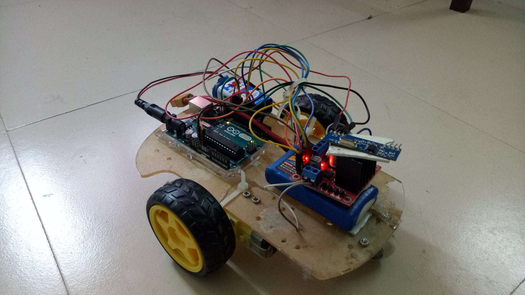

here is a hand controller gesture control car, made by using mpu6050 and arduino. I use rf module for wireless connection.
Step 1: THINGS REQUIRED :


•1.arduino uno
•2.micro Arduino
•3.rf module(transmitter and receiver)
•3.mpu6050(accelomitter)
•4.motor driver
•5.2 dc motor
•6.robotics chassis
•7. Arduino cable
•8.one hand glapse
•9. motor driver
•10. LiPo Battery
•11. 9V battery
12.USB cable
Step 2: Connection:-

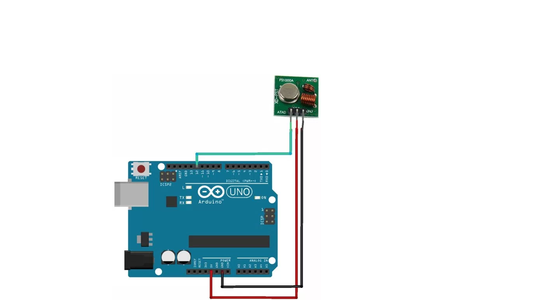
•1.connection for rf transmitter:-
•GND = GND
•DATA = 12
•VCC = 5V
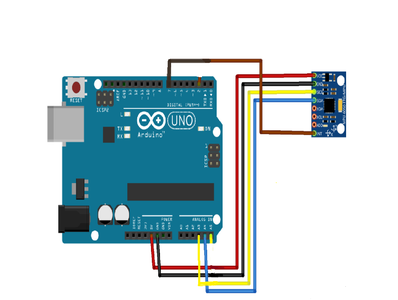
•2.connection for mpu6050:-
•VCC = 3.3/5v
•GND = GND
•SCL = A3
•SDA = A2
•INT = 7
•mpu6050 need 3.5V voltage.but we can give it 5V voltage.i give here 3.5V voltage to mpu6050 because in micro arduino there
•are two voltage pin first is 5V and another one is 3.3V.rf reciever have to need 5V.so i use 5V pin for rf transmitter.and
•mpu6050 can run 3.5V.
•3.connection for rf receiver:-
•GND = GND
•DATA = 12
•VCC = 5V
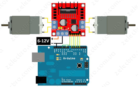
•4.connection for motor driver:-
•motor one:-
•int enA = 11
•int in1 = 7
•int in2 = 6
•motor two:-
•int enB = 3
•int in3 = 5
•int in4 = 4
Step 3: Working Principal:-

1.mpu6050:-
MPU-6050 Triple Axis Accelerometer and Gyro Breakout Board.it read three angles.we can give them name X, Y, and Z, here we
use here only two angles. here we use Y and Z.Y for forward and Z for left, right.
this part of code read the angle.
•mpu-6050
reads the angles in radian, this "* 180/M_PI" make it in degree.
Step 4: •Rf Transmitter:-

•Rf
transmitter:-
Mpu6050 read the angles. then I make one “if” loop and make a condition.in then make two buffer.one buffer sends condition for forward. and in the second one, I send the angle, for control the speed by the angle. this part of code sends the message. And I map the angle.

Step 5: RF RECEIVER:-

•Rf receiver:-
the receiver receives the message in the buffer. Again I make a condition on the first buffer for forward. And the second one I use for control the speed. And I again map it. This part of the code is doing this work. and for the speed control, I use the second buffer and, the angles mapped (0,9), I map speed in (50,255). you can see all things in code.
Step 6: Let's Run the Car:-

- now the time has come to run the robot.make sure that all connection is correct. now connect your glapse's micro arduino to your computer. open the serial monitor, now you can see angles reading.now send any input from the transmitter to the receiver. now your robot is ready for a run.
Step 7:
if you fill difficulty in those codes. you can use these code. I make these because I fill you will difficulty fill in the transmitter code. so I make these easy code. and you won't need to follow 6th step. just connect the power the transmitter's Arduino and your robot is in your control.

Participated in the
Arduino Contest 2017

Participated in the
Remote Control Contest 2017


