

Introduction: Gesture Control Car(robot) With Arduino and Android(bluetooth)
Hi folks,
Here's an interesting project for all you creative minds out there. We are going to build an android phone controlled RC car.
Nothing could be more fascinating than remote controlled cars. This one uses Bluetooth for communication and accelerometer of the mobile device for gesture control.
The reason behind the use of a mobile is its versatility and the omnipresence. This mobile device has a great scope in future robotics especially in the control. The use of mobile makes it very easy to control because it can control more than one device at a time with an application using sensors and technology inbuilt.
So bring out the engineer in you and ENJOY!!!
Happy making!!!
Step 1: Selection Guide for Parts:


Instead of providing list directly, I try to explain how parts should be selected. so that you can use any other part if you already have one.
Arduino:
The Arduino is a small development board with a brain (also known as a micro controller) that you can program. It interacts with the real world through LEDs, sensors, motors, LCDs, buzzers, etc. Arduino is essentially a tiny computer that can connect to electrical circuits. There are many other development boards available in the market, but Arduino is more preferable as it is open source, very versatile and easy to use. You can find more detail about Arduino on their website provide below:
Android:
There are many smart phone available in market. Android is more suitable for such a DIY because of its popularity. We can connect any module or device to android easily rather than iPhone or windows phone. Play store has many app for Bluetooth and Wi-Fi control. For this DIY, we need an android smart phone with Bluetooth.
Motor and driver IC:
There are many types of motors available in the market like servomotor, stepper motor etc. Each one have their different pros and cons. There are many manufacturer. I have used stepper dc motors provided by Johnson for this project. You can use Vega motors also. Johnson has a more torque than Vega, but it requires more current. Vega is cheaper than Johnson. Servomotor is used where precise control of angular velocity, position and acceleration is required.
Selection of motor driver IC is depend on the motor you use. Each motor driver IC have different specifications. You can find detailed specification on manufacturer’s website. For use with Johnson, I have L298N. You can use L293D with Vega motors.
Chassis and wheels:
Selection of chassis is depend on type of bot you are making. You can make 2-wheels or 4-wheels car or bot. you can buy readymade chassis or make one from wooden scrap. If you will make one from plywood, you would have required clamps for motor. Wheels are available in various diameter and width. You can buy 2 or 4 according to your need. 4-wheeler car is more stable and strong to bear heavy weight of chassis and battery but it required more space to turn around. While 2-wheeler car required small distance to turn.
Bluetooth:
We can use different types of Bluetooth module like hc-05 or hc-06 in this DIY. One can find data sheet for both the module on internet.
Battery:
There are different types of rechargeable battery available like li-polymer, li-ion, pb-acid, etc. they are in different mAH and voltage. One can choose from them according to cost and requirement.
Final list of parts and tools required:
· 1x Arduino Uno r3
· 1x Bluetooth module hc05
· 1x motor driver IC L298N
· 4x Johnson motor (of any rpm you want)
· 1x chassis
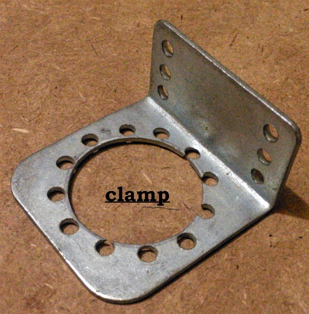
· 4x clamp for Johnson
· 1x rechargeable battery 12V for IC
· 1x battery 9V for Arduino
· Screws and bolts
· Jumper cables (male to male connectors)
· wire
· Female pins
· Bread board
· Multimeter(not necessary)
· Circuit board(small)
· Soldering iron and wire
Step 2: How It Works
There are main three parts in any wireless circuit:
1. Transmitter(android phone)
2. Receiver(Bluetooth module)
3. Decoder and controller(Arduino board)
Step 3: Clamp the Motor With Chassis


Clamp all four motors with chassis with the help of clamp as shown above. Make sure that all the four wheels are aligned correctly as we will use the rotation of either side of wheels of car to turn it in any direction.
Step 4: Circuit Diagram
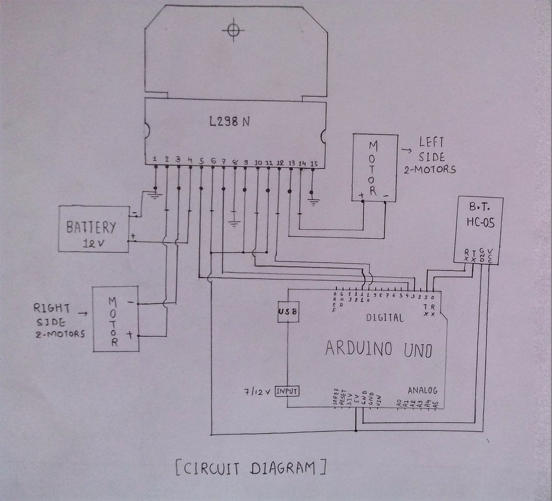

I insist you to connect whole circuit on breadboard before
soldering it on circuit board because there is a chance to make mistakes in connection at first try. Before moving forward, I would suggest you to refer specification of all electronics part.
Connect circuit as shown in figure on bread board with driver IC, Arduino Uno r3, Bluetooth hc05. Connect motors in the output terminals.
Attachments

Step 5: Upload the Sketch to Arduino

You can load new programs onto the main chip - ATmega328p – of Arduino Uno r3 via USB using the Arduino IDE. Visit the link below to download the latest Arduino IDE:
http://arduino.cc/en/Main/Software
The official Arduino website does a great job explaining how to do it any of the three operating systems (Windows, Mac and Linux).
Connect your Arduino UNO to your computer via USB. Open your Arduino IDE. Open the file attached below.
By default your Arduino IDE comes pre-configured for the Arduino UNO. Make sure that you have selected the right port. If you haven’t then you can change it from tools menu. Bottom right corner of IDE of Arduino shows the current configuration.
Left-click the “Upload” button and wait a few seconds until a “Done uploading.” message appears. You don’t required to reset Arduino Uno r3 before uploading a new sketch because it is itself replace the earlier sketch with new one.
Two common mistakes
1. You need to remove the RX and TX cables when you're uploading the sketch to your Arduino.
2. Sometimes people connect the TX from the Bluetooth module to the TX of the Arduino... that's wrong and it won't work. Make sure you connect it properly, the TX into RX and the RX into the TX.

Step 6: Android App

You can write application for this if you are developer. You can easily find source code for this. But as I am not a developer, I would better preferred to search for app on play store. I have provided link to download app which suits better with this DIY.
You can also use any other app by modifying the code which is uploaded on Arduino.
APP: BLUETOOTH ROBOT CAR CONTROLLER by hobbyprojects.com available on play store.
Step 7: Pair and Connect Bluetooth

You have to pair your phone’s Bluetooth with Bluetooth module HC05 before you connect it from application.
Power the circuit or Bluetooth and then go to menu>> settings>> Bluetooth. Turn it on and search for nearby devices. Find HC05 and pair it.
Note: If the HC-05 Bluetooth Module asks for a password, it’s '1234'.
After pairing the Bluetooth module with phone’s Bluetooth, start the application. Touch on select device and select HC05 from it. Prompt shows that device connected successfully.at that time keep mobile parallel, screen upwards.
Now move phone in forward, backward, left and right direction and make sure that motors working properly in each movement. If it rotates in wrong directions, you have to correct it by interchanging positive and negative terminal of motors.
Step 8: Soldering and Connections

After verifying that
circuit works perfectly, now it’s time to solder circuit on circuit board. For this step you required soldering skills. If you haven’t then learn it first.
After soldering IC and female pin as shown in figure, fit circuit board, Arduino and Bluetooth on chassis with battery. Place these things so that centre of mass remain at the centre of chassis.
Now connect circuit as we did in 2nd step.
Step 9: Play and Have Fun!


Power the circuit and start app. Connect phone with module.
You are ready to go!
Play and have fun!
I have uploaded one another video. Which help you understand how you can use this same concept for other robots.
This robot-car was built for participating at TECHFEST- KSHITIJ 2015 at IIT KGP. The car won the award for BEST CONCEPT AND DESIGN.
This bot incorporates a metal detector and a gripper mechanism. It can be controlled by 2 mobile devices simultaneously.
You can add many other sensors and mechanism according to your need. All you need to do is small modification in coding and circuit and its work perfectly.
After you create something cool, I hope you share with others. That’s the whole goal of this awesome maker movement.
Write in comment box if you need further explanation.
Thank you!!!

Participated in the
Move It


