

Introduction: Getting Started With Nextion and Arduino Uno (pt. 2)


Hi all,
In the previous instructable we saw how to see (on the Arduino) if a single button was tapped on the Nextion. We did this without using a library.
Now I would like to show you one way of receiving and interpreting data received from the Nextion. Once again we will do this without the library. I am doing it without the library, because it my sketches wouldn't compile when I added the library.
In part 3 we will also see what issue we are faced with when sending more than 1 component ID or value and how to work around it.
Step 1: What You'll Need
- Your Nextion display (I used a 2.8" model).
- 4 male-male jumper wires.
- An Arduino Uno.
- A cable for connecting your Arduino to the PC.
- Your PC with the Arduino IDE and the Nextion editor installed.
- A SD card and adapter for your PC to read the card.
Step 2: Making Your Interface
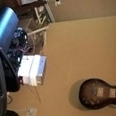
This interface is somewhat more complex than the previous interface. Download the attached interface and I'll point out things to note:
- Note the code in the "Pre-initialize event" of the page.
- The + and - buttons have code in them to make sure negative numbers cannot be entered.
- The submit (aka. fly Shadowfax!) button converts the numerical value to text and sends it to the Arduino. See below on why we convert to text.
- The code in the Nextion Editor is very sensitive to spaces. I've found that the Nextion Instruction Set shows spaces, but the editor freaks out over this.
- Compile the interface and copy it to your SD card.
I've found it easier to convert numerical values to text, because text is sent as ASCII codes to the Arduino. Numerical values is sent in a way that I don't know (see the instruction set). Text is also easier to manipulate than numeric values and this eases the interpretation at the Arduino side.
Attachments

Step 3: Understand How Data Is Sent

Now we'll take a moment to understand how data is sent.
- Open the HMI file again.
- Go to debug (Under the menu bar there is a toolbar. The debug button is there).
- Your interface is now being simulated. Play around to see what happens.
- You'll notice when you click "Fly Shadowfax!" some data is spit out into the "Simulator Return data" (middle-bottom of the screen).
- If you submitted '5' the data will be 0x70 0x35 0xff 0xff 0xff. These are hexadecimal pieces of data and each has a meaning.
- 0x70 = indicates that this message is text.
- 0x35 = hexadecimal for the number '5'.
- 0xff = repeated 3 times to show that this is the end of this message.
- This data is transferred bit by bit through the serial port. As we'll see we will have to reconstruct the bits into one message on the Arduino.
Step 4: Upload the Sketch

I've tried to add enough comments to the sketch to make it understandable. The idea of this sketch is to capture the data coming from the Nextion, extract the parts which are important to us, assign a value to a variable and do some comparison on the Arduino.
If you would like to go further with this sketch we could, for example, add an LED which turns on and off based on the value that is being sent to the Arduino from the Nextion.
Attachments
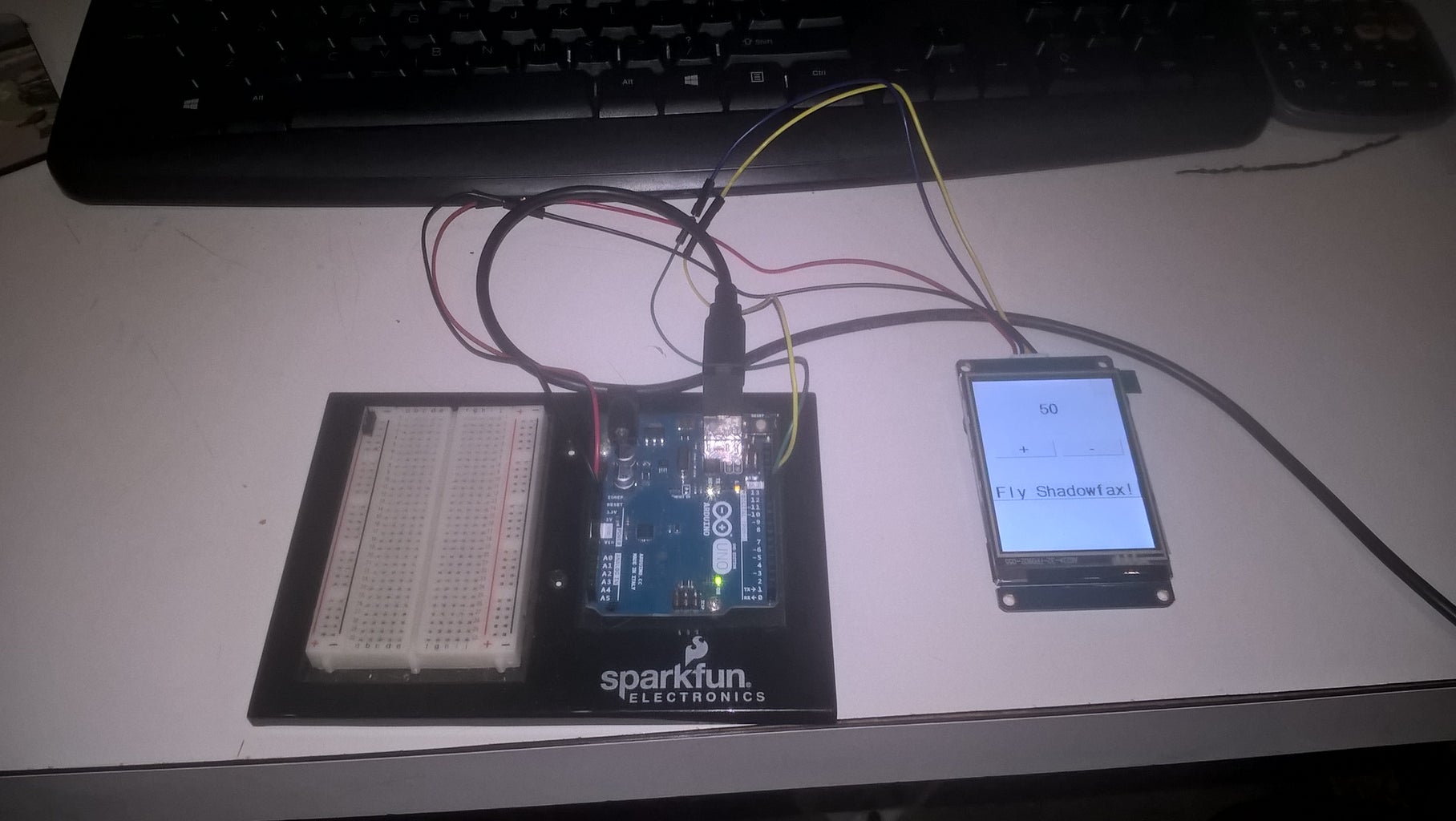
Step 5: Connect Your Nextion to the Arduino
Connect the red and black wires to 5V and ground on the Arduino respectively. Connect the blue (TX) wire of the Nextion pin 10 and the yellow (RX) wire to pin 11.
Step 6: Understand How Data Is Received
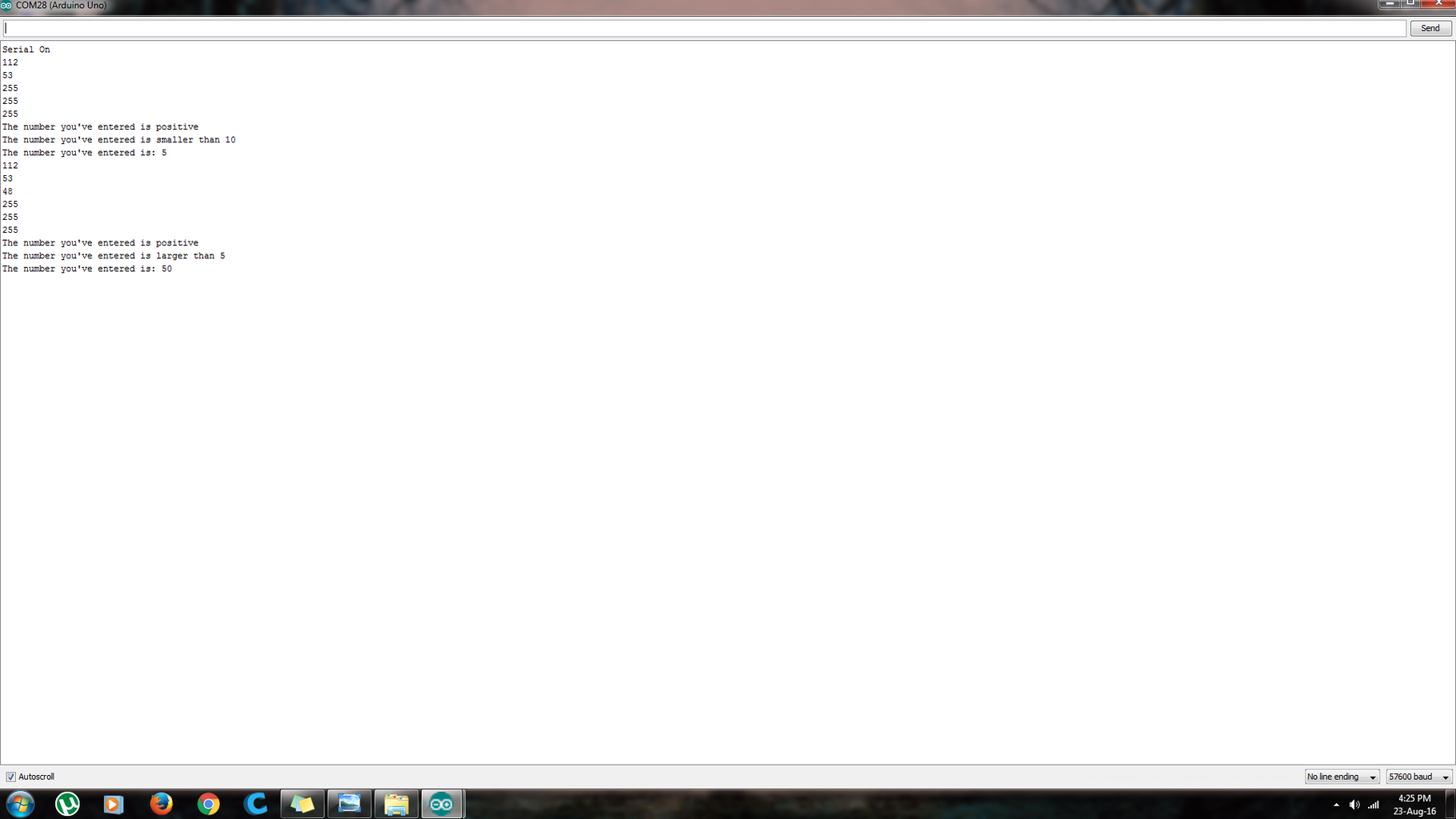
If you open the serial monitor of the Arduino and set is to 57600 baud, you'll see the data coming in from the Nextion. It looks quite different from the data we saw in the simulation done in Nextion Editor, doesn't it? This is because all the data is converted from hexadecimal to decimal. Using this converter we can convert the data from Nextion Editor into decimal and compare it to what we see in the serial monitor.
If you have submitted '5' your data will come out as:
- 112 53 255 255 255.
- 112 - indicates the start of the message.
- 53 - decimal value for ASCII '5'.
- 255 - repeated 3 times to indicate the end of the message.
If you have submitted '50' your data will come out as:
- 112 53 48 255 255 255.
- Everything is the same as above, except for the extra '48'.
- 48 - decimal value for ASCII '0'.
Because the data is sent sequentially, we can capture the bits that matter to us, and disregard the rest.
Step 7: Finished
Open your serial monitor and set the baud rate to 57600. Try sending different numbers to the Arduino and see what the output is!


