

Introduction: GroveWeatherPi - Solar Raspberry Pi Based Weather Station - No Soldering Required (Updated October 24, 2016)


Updated Kit to SkyWeather May 27, 2019
(SkyWeather Page)
Building a Solar Powered Raspberry Pi Weather Station - GroveWeatherPi (Updated March 12, 2017) - See Update In Next Section
Software and Hardware Update March 12, 2017
The Raspberry Pi is a fabulous device to on which to build your projects. The GroveWeatherPi project is designed to show the capabilities of this computer while remaining accessible to a diverse Maker community.
The key to keeping this project accessible to many people is to minimizing the need for complex wiring and soldering. In this tutorial, we are showing how to build Raspberry Pi based Weather Station in two parts (actually 13 steps). The first major part is building the GroveWeatherPi station itself. This can be done with no soldering. The second part of the tutorial is outfitting your GroveWeatherPi with Solar panels. This can be done with a very minimal amount of soldering to produce a fully solar powered Raspberry Pi based weather station.
(Update: Grove Sunlight Sensor - SI1145 now supported - measures visible light, IR and UV)
What is GroveWeatherPi?
GroveWeatherPi is a Solar Powered Raspberry Pi WiFi connected weather station designed for Makers by SwitchDoc Labs ( www.switchdoc.com). This is a great system to build and tinker with. All of it is modifiable and all source code is included.
This tutorial for building your own Solar Powered Weather Station based on the Raspberry Pi consists of 13 steps.
Features
The most important functions are:
- Detects Lightning!
- Senses 20 different environmental values
- Optionally Solar Powered
- Has a full database containing history of the environment (MySQL)
- Monitors and reports lots of data on the solar powered system - great for education!
- Self contained and monitored for brownouts and power issues
- Can be modified remotely
- Download your data to crunch it on your PC or Mac
- Can be modified to do CWOP, SMS (Text) messaging, Twitters, webpages and more
- Has an iPad Based Control Panel
- Easy to connect to Twitter, WeatherUnderground, etc
This chapter will show you how to build a WiFi Solar Powered Raspberry Pi Weather Station. This project grew out of a number of other projects, including the massive Project Curacao ( www.switchdoc.com/project-curacao-introduction-part-1/), a solar powered environmental monitoring system deployed on the Caribbean tropical island of Curacao. Project Curacao was written up in an extensive set of articles in MagPi magazine (starting in Issue 18 and continuing through Issue 22) as well as issues of Raspberry Pi Geek Magazine.
Educational Objectives
The GroveWeatherPi Solar Powered Weather Station is an excellent education project. There are many aspects of this project that can be looked at and analyzed for educational purposes:
- How do solar power systems behave? Limitations and advantages
- Temperature, Wind and Humidity data analysis.
- Shutting down and starting up small computers on solar power
- Add your own sensors for UV, dust and pollen count and light color
- Follow along on updates to the GroveWeatherPi story on www.switchdoc.com
What You Will Be Building
You will building a Raspberry Pi based Weather Station using the new standard for easily prototyping and building electronics and software projects, the Grove Connection System. Then you will be adding a solar power to the Weather Pi.
What is the Grove Prototyping System?
Grove is a modular, standardized connecter prototyping system. Grove takes a building block approach to  assembling electronics. Compared to the jumper or solder based system, it is easier to connect, experiment and build and simplifies the learning system, but not to the point where it becomes dumbed down. Some of the other prototype systems out there takes the level down to building blocks. Good stuff to be learned that way, but the Grove system allows you to build real systems. It requires some learning and expertise to hook things up.
The Grove system consists of a base unit (stem) and various modules (twigs) with standardized connectors. The people originating the Grove system (Seeedstudio) have tried to use “stems” and “twigs” as part of the Grove lexicon. After a short period of consideration, We are dropping those names. They just aren’t needed and just confuse the issue.
The Base unit, generally a microprocessor, allows for easy connection of any input or output from the Grove modules. and every Grove module typically addresses a single function, such as a simple button or a more complex heart rate sensor.
You don’t need a Base unit to connect up to Grove modules. You an use a cable (Grove to Pin Header Converter) to run from the pins on the Raspberry Pi or Arduino to the Grove connectors. We use the Pi2Grover Grove to Raspberry Pi Interface in the GroveWeatherPi project.
Here is our full Grove Tutorial.
So what is a Grove Connector?
]
A Grove connector is a four pin standardized size connector used to plug into base units and Grove modules. The  picture above shows the male Grove Connector. The male connectors come in flat 90 degree versions and vertical versions as in Figure 2. Seeedstudio has the exact dimensions in this specification ( http://www.seeedstudio.com/http://www.seeedstudio.com/wiki/images/6/69/3470130P1.pdf). These standardized connectors (common to all types of Grove Connectors) are the key to making this system work. They are keyed to prevent plugging them in backwards, and the four types of connectors (see below) are all designed so that if you plug the wrong type of device into the wrong type of base unit, there is no problem. They just won’t work. This is a good thing.
The one exception would be if you plugged in a 3.3V I2C Grove module that is non-5V tolerant into a 5V I2C Grove connector you could fry the device.
Description of the Weather Pi Project
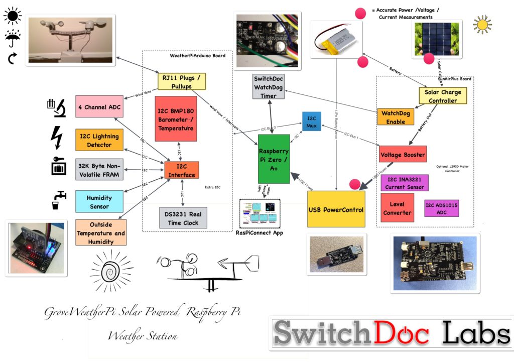 GroveWeatherPi Block Diagram
The GroveWeatherPi Block Diagram looks a lot more complicated than it actually is.
The first thing to notice that the dashed lines are individual boards (Weather Board and SunAirPlus) which contain a lot of the block diagram and the second thing is that all of the sensors to the left of the diagram plug into the Weather Board board which simplifies the wiring. Don't be intimidated!
Virtually all of these wires are based on Grove Connectors.
The Subsystems
The Sensor Subsystem of GroveWeatherPi uses a WeatherBoard as the base unit and then plugs in a bunch of optional sensors such as wind speed, direction and rain and lightning detection (how cool is that!), inside and outside temperature and humidity as well as barometric pressure.
The Software Subsystem of GroveWeatherPi runs in Python on the Raspberry Pi. It collects the data, stores in in a MySQL database, builds graphs and does housekeeping and power monitoring.
The Solar Power Subsystem of GroveWeatherPi uses a SunAirPlus Solar Power Controller which handles the solar panels, charging of the battery and then supplies the 5V to the Raspberry Pi and the rest of the system. It also contains sensors that will tell you the current and voltage produced by the Solar Panels and consumed by the batteries and the Raspberry Pi. Gather that Data! More Cowbell! It also contains the hardware watchdog timer and the USB PowerControl that actually shuts off the power to the Raspberry Pi during a brownout event (after the Pi shuts gracefully down under software control).
If you are not building the optional Solar Power system, then you can just plug in a normal Raspberry Pi power supply and then you have a fully functional powered weather station.
The GroveWeatherPi Sensor Suite
The GroveWeatherPi Sensor Suite senses the following environmental values:
- Wind Speed
- Wind Direction
- Rain
- Outside Temperature
- Outside Humidity
- Lightning Detection
- Barometric Pressure (and Altitude)
- Inside Box Temperature
- Inside Box Humidity
You can add more to the I2C bus and Analog to Digital Converter such as UV, dust counts, light color (sensing some types of pollution) and more! It's a great platform for expansion.
The sensor suite is built on the Weather Board board but there are several similar boards out there on the market.
Step 1: What Are All the Sensors on the Grove Weather Pi?

The GroveWeatherPi has 16 different environmental sensors built into the project. The system is designed to be expandable so you can add many more sensors.
The sensor list:
- Lightning Detection
- Outside Temperature
- Outside Humidity
- Inside Temperature
- Barometric Pressure
- Inside Humidity (optional - requires soldering)
- Battery Voltage
- Solar Panel Voltage
- Raspberry Pi Power Voltage
- Battery Current
- Solar Panel Current
- Raspberry Pi Current
- Wind Speed
- Wind Gust
- Rain Amount
- Wind Direction
The GroveWeatherPi is heavily based on Grove I2C Sensors.
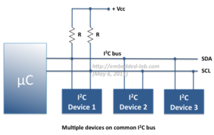
What is an I2C Bus and What is On the Bus?
An I2C bus is often used to communicate with chips or sensors that are on the same board or located physically close to the CPU. It stands for standard Inter-IC device bus. I2C was first developed by Phillips (now NXP Semiconductors). To get around licensing issues, often the bus will be called TWI (Two Wire Interface). SMBus, developed by Intel, is a subset of I2C that defines the protocols more strictly. Modern I2C systems take policies and rules from SMBus sometimes supporting both with minimal reconfiguration needed. The Raspberry Pi is one of these devices.
I2C provides good support for slow, close peripheral devices that only need be addressed occasionally. For example, a temperate measuring device will generally only change very slowly and so is a good candidate for the use of I2C, where a camera will generate lots of data quickly and potentially changes often.
I2C uses only two bi-directional open-drain lines (open-drain means the device can pull a level down to ground, but can not pull the line up to Vdd. Hence the name open-drain. Thus a requirement of I2C bus is that both lines are pulled up to Vdd. This is an important area and not properly pulling up the lines is the first and most common mistake you make when you first use an I2C bus. More on pullup resistors later in the next section. The two lines are SDA (Serial Data Line) and the SCL (Serial Clock Line). There are two types of devices you can connect to an I2C bus. They are Master devices and Slave devices. Typically, you have one Master device (The Raspberry Pi in our case) and multiple Slave devices, each with their individual 7 bit address ().
When used on the Raspberry Pi, the Raspberry Pi acts as the Master and all other devices are connected as Slaves.
The I2C protocol uses three types of messages:
- Single message where a master writes data to a slave;
- Single message where a master reads data from a slave;
- Combined messages, where a master issues at least two reads and/or writes to one or more slaves.
Lucky for us, most of the complexity of dealing with the I2C bus is hidden by drivers and libraries from the user.
Pullups on the I2C Bus
One import thing to consider on your I2C bus are pullup resistors. The Raspberry Pi has 1.8K ohm (1k8) resistors already attached to the SDA and SCL lines, so you really shouldn't need any additional pullup resistors. However, you do need to look at your I2C boards to find out if they have pullup resistors. If you have too many devices on the I2C bus with their own pullups, your bus will stop working. The rule of thumb from Phillips is not to let the total pullup resistors in parallel be less than 1K (1k0) ohms. The GroveWeatherPi has build in pullup resistors on all the I2C buses.
The I2C Bus on Weather Pi
At SwitchDoc Labs, we love data. And we love I2C devices. We like to gather the data using lots of I2C devices on our computers and projects. Project Curacao has a total of 12, GroveWeatherPi has 11 devices and SunRover (a solar powered rover under development at SwitchDoc - you will see it in 2017) will have over 20 and will require one I2C bus just for controlling the motors. We are always running into conflicts with addressing on the I2C device. Since there are no standards, sometimes multiple devices will have the same address, such as 0x70 and you are just out of luck in running both of them on the same I2C bus without a lot of jimmy rigging.
To get around this addressing problem (and our conflict with an INA3221 on SunAirPlus and the Inside Humidity Sensor) we added an I2C Bus Multiplexer to the design which allows us to have many more I2C devices on the bus, irregardless of addressing conflicts. Here is our current list of I2C devices in GroveWeatherPi including which I2C bus the devices is on in the GroveWeatherPi design:
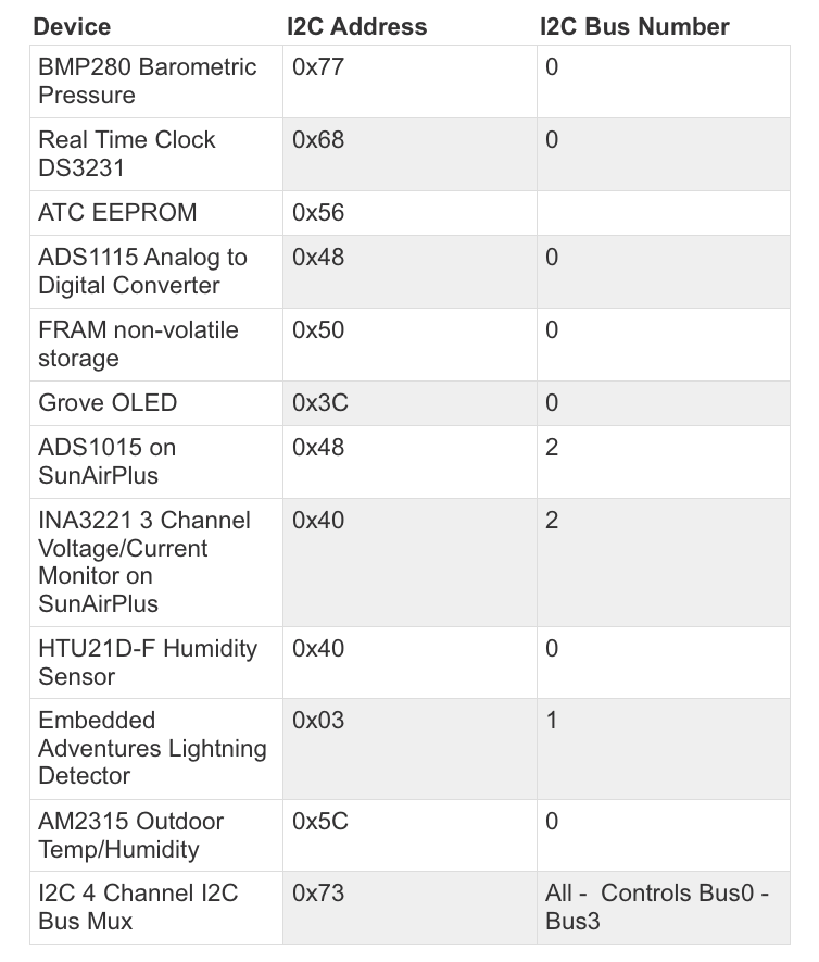
Note that GroveWeatherPi only uses Bus 0, Bus 1 and Bus 2.
Here is what the I2C bus looks like on the Raspberry Pi after assembling the GroveWeatherPi project. This is the output from the example code with the I2C 4 Channel Mux (hence there are 4 independent busses shown for the I2C bus).
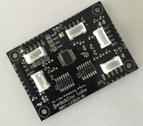
4 Channel Grove I2C Mux
Test SDL_Pi_TCA9545 Version 1.0 - SwitchDoc Labs

Sample uses 0x73
Program Started at:2016-08-03 21:50:40

-----------BUS 0-------------------
tca9545 control register B3-B0 = 0x1
ignore Interrupts if INT3' - INT0' not connected
tca9545 control register Interrupts = 0x0
     0  1  2  3  4  5  6  7  8  9  a  b  c  d  e  f
00:          -- -- -- -- -- -- -- -- -- -- -- -- --
10: -- -- -- -- -- -- -- -- -- -- -- -- -- -- -- --
20: -- -- -- -- -- -- -- -- -- -- -- -- -- -- -- --
30: -- -- -- -- -- -- -- -- -- -- -- -- 3c -- -- --
40: 40 -- -- -- -- -- -- -- 48 -- -- -- -- -- -- --
50: -- -- -- -- -- -- -- 57 -- -- -- -- -- -- -- --
60: -- -- -- -- -- -- -- -- 68 -- -- -- -- -- -- --
70: -- -- -- 73 -- -- -- 77

-----------------------------------

-----------BUS 1-------------------
tca9545 control register B3-B0 = 0x2
ignore Interrupts if INT3' - INT0' not connected
tca9545 control register Interrupts = 0x0
     0  1  2  3  4  5  6  7  8  9  a  b  c  d  e  f
00:          03 -- -- -- -- -- -- -- -- -- -- -- --
10: -- -- -- -- -- -- -- -- -- -- -- -- -- -- -- --
20: -- -- -- -- -- -- -- -- -- -- -- -- -- -- -- --
30: -- -- -- -- -- -- -- -- -- -- -- -- -- -- -- --
40: -- -- -- -- -- -- -- -- -- -- -- -- -- -- -- --
50: -- -- -- -- -- -- -- -- -- -- -- -- -- -- -- --
60: -- -- -- -- -- -- -- -- -- -- -- -- -- -- -- --
70: -- -- -- 73 -- -- -- --

-----------------------------------

-----------BUS 2-------------------
tca9545 control register B3-B0 = 0x4
ignore Interrupts if INT3' - INT0' not connected
tca9545 control register Interrupts = 0x0
     0  1  2  3  4  5  6  7  8  9  a  b  c  d  e  f
00:          -- -- -- -- -- -- -- -- -- -- -- -- --
10: -- -- -- -- -- -- -- -- -- -- -- -- -- -- -- --
20: -- -- -- -- -- -- -- -- -- -- -- -- -- -- -- --
30: -- -- -- -- -- -- -- -- -- -- -- -- -- -- -- --
40: 40 -- -- -- -- -- -- -- 48 -- -- -- -- -- -- --
50: -- -- -- -- -- -- -- -- -- -- -- -- -- -- -- --
60: -- -- -- -- -- -- -- -- -- -- -- -- -- -- -- --
70: -- -- -- 73 -- -- -- --

-----------------------------------

-----------BUS 3-------------------
tca9545 control register B3-B0 = 0x8
ignore Interrupts if INT3' - INT0' not connected
tca9545 control register Interrupts = 0x0
     0  1  2  3  4  5  6  7  8  9  a  b  c  d  e  f
00:          -- -- -- -- -- -- -- -- -- -- -- -- --
10: -- -- -- -- -- -- -- -- -- -- -- -- -- -- -- --
20: -- -- -- -- -- -- -- -- -- -- -- -- -- -- -- --
30: -- -- -- -- -- -- -- -- -- -- -- -- -- -- -- --
40: -- -- -- -- -- -- -- -- -- -- -- -- -- -- -- --
50: -- -- -- -- -- -- -- -- -- -- -- -- -- -- -- --
60: -- -- -- -- -- -- -- -- -- -- -- -- -- -- -- --
70: -- -- -- 73 -- -- -- --
Step 2: Sizing Your Solar Power Weather Station


Sizing Your Solar Power System
One of the first things that comes up in a solar powered design is how to design the power system. The three main questions to be asked and answered are:
1. How much power do I need?
2. How many solar panels do I need?
3. What size battery do I need?
The first thing you need to do when designing a solar powered system is to determine the power requirements for your solar powered design. Our criteria is that we want the GroveWeatherPi Raspberry Pi to run all day and during the night. But we want the system to able to shutdown and restart itself when power is available.
The table below contains estimated power consumption for models of the Raspberry Pi, including a Wireless USB dongle. We are assuming in each of these that you turn the HDMI port off which saves ~20ma.
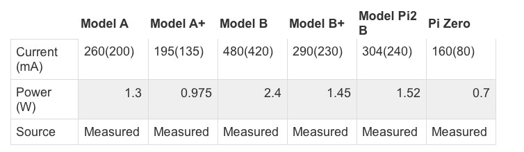
All of the above measurements include about 60ma for the USB WiFi Dongle! Parenthetical numbers are without the 60ma.
Based on the above, first we will lay out our assumptions for our Raspberry Pi Model A+ based design. The LiPo batteries chosen will store 6600mAh. Why choose the Model A+? It's the lowest current consuming raspberry Pi that doesn’t require soldering.
SOLDERING NOTE: If you want to use a Raspberry Pi Zero, you will need to solder a 40 pin connector on the board. Choosing a Model A+ reduces the need for soldering.
What is mAh (milli Amp hours)? 6600mAh means you can take 100mA for 66 hours, theoretically. In actuality, you will not be able to get more than about 80% on average depending on your battery. How fast you discharge them also makes a big difference. Slower the discharge rate, the more mAh you can get out of the battery. For comparison, an AA battery will hold about 1000mAh ( http://en.wikipedia.org/wiki/AA_battery ) and a D battery will hold about 10000mAh ( http://en.wikipedia.org/wiki/AA_battery ).
In a system like this, it is best to charge your LiPo batteries completely and then hook up the computer and see how long it takes to discharge the battery and die. We did this test on the GroveWeatherPi system. The results are on switchdoc.com ( http://www.switchdoc.com/2015/04/figuring-out-when-to-shutdown-your-solar-powered-raspberry-pi-weatherpi/ ).
Raspberry Pi A+ Solar Design
Assumptions:
- Two Voltaic 3.4W 6V/530ma Solar Cells (total of 6.8W)
- 8 Hours of Sun running the cells at least at 70% of max Delivery of current to Raspberry Pi at 85% efficiency (you lose power in the charging and boosting circuitry)
- Raspberry Pi Model A+ takes 195mA on average (with the Wireless USB Dongle)
- Raspberry Pi Model A+ running 24 hours per day
- 6600mAh LiPo Batteries
Given these we can calculate total Raspberry Pi Model A runtime during a typical day: PiRunTime = (8 Hours * 70% * 1060mA) *85% / (195mA) = 25 hours.
Our goal was for 24 hours, so it looks like our system will work. 16 Hours of running the Raspberry Pi Model A+ on batteries alone will take (195mA/85%)*16 Hours = 3670mAh which is comfortably less than our 6600mAh batteries can store. The WIFI dongle added about 60mA on average. It was enabled the entire time the Raspberry Pi was on. No effort was made to minimize the power consumed by the WiFi dongle. Your results will depend on what other loads you are driving, such as other USB devices, GPIO loads, I2C devices, etc.
Note that during the day, on average, we are putting into the battery about 6000mAh. This also means a bigger battery than 6600mAh will not make much difference to this system.
So, on a bright sunny day, we should be able to run 24 hours a day. Looking at the results from GroveWeatherPi being out in the sun for a week, this seems to be correct. However, it will be cloudy and rainy and your system will run out of power. The next most important part of the design is how to handle Brownouts! See a step later in this Instructable about how to hand this nasty little problem.
Raspberry Pi Zero Solar Design
Assumptions:
- Two SwitchDoc Labs 2W 6V/330ma Solar Cells (total of 4W)
- 8 Hours of Sun running the cells at least at 70% of max Delivery of current to Raspberry Pi at 85% efficiency (you lose power in the charging and boosting circuitry)
- Raspberry Pi Model Zero takes 160mA on average (with the Wireless USB Dongle) - Removed OLED display.
- Raspberry Pi Model Zero running 24 hours per day
- 6600mAh LiPo Batteries
Given these we can calculate total Raspberry Pi Model Zero runtime during a typical day: PiRunTime = (8 Hours * 70% * 660mA) *85% / (160mA) = 23.1 hours. Adding another inexpensive 2W solar panel would bring this to 34 hours. Since we are so close to the 24 hours with two, let’s go with two for this design and spend a bit of time in the future figuring out how to shut off the WiFi for part of the time to make up the difference.
Our goal was for 24 hours, so it looks like our system will pretty much work. 16 Hours of running the Raspberry Pi Zero on batteries alone will take (160mA/85%)*16 Hours = 3011mAh which is comfortably less than our 6600mAh batteries can store. The WIFI dongle added about 60mA on average. It was enabled the entire time the Raspberry Pi was on. No effort was made to minimize the power consumed by the WiFi dongle. Your results will depend on what other loads you are driving, such as other USB devices, GPIO loads, I2C devices, etc.
Note that during the day, on average, we are putting into the battery about 6000mAh. This also means a bigger battery than 6600mAh will not make much difference to this system.
So, on a bright sunny day, we should be able to run 24 hours a day. Looking at the results from GroveWeatherPi being out in the sun for a week, this seems to be correct. However, it will be cloudy and rainy and your system will run out of power. The next most important part of the design is how to handle Brownouts! See a step later in this tutorial about how to hand this nasty little problem.
Solar System Design
The four most important parts of verifying your Solar Power Design:
- Gather real data
- Gather more real data
- Gather still more real data
- Look at your data and what it is telling you about the real system. Rinse and Repeat.
The power system in Weather Pi consists of four parts:
- Two Solar Panels
- One 6600Ah LiPo Battery
- SunAirPlus Solar Power Controller, Pi Power Supply and Data Gathering system
- USB PowerControl board for Raspberry Pi Power Control
We are using 2 2W/330mA Solar Panels from SwitchDoc Labs. You can use virtually any solar panel as long as they are 6V solar panels. And if you find that your unit is still not getting enough power during the day, then add another 2W panel!. The Voltaic Systems panels will run you about $40 a piece where the SwitchDoc Labs Panels will cost about $12 per panel. We have a lot of experienced with the Voltaics panels in the tropics and they are good panels.
We selected a 6600mAh battery from Adafruit for this design. See the "Sizing your Solar System" step above. We are using a SunAirPlus Solar Power Controller in this design.
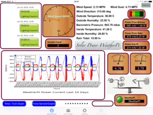
SunAirPlus includes an I2C INA3221 3 Channel Current / Voltage Monitor and a I2C 4 channel 12 bit Analog to Digital Converter (ADS1015). The INA3221 allows you to monitor all of the major currents and voltages in the system (Battery / Solar Panels / Load - Computer ). You can tell what your solar power project is doing in real time.
SunAirPlus Results
Here are some results from the SunAirPlus board using the onboard INA3221. You can see that the battery is almost fully charged and the solar cell voltage (actually a variable power supply on the test bench) is 5.19V and it is supplying 735mA.Test SDL_Pi_INA3221 Version 1.0 - SwitchDoc Labs Sample uses 0x40 and SunAirPlus board INA3221 Will work with the INA3221 SwitchDoc Labs Breakout Board ------------------------------ LIPO_Battery Bus Voltage: 4.15 V LIPO_Battery Shunt Voltage: -9.12 mV LIPO_Battery Load Voltage: 4.14 V LIPO_Battery Current 1: 91.20 mA Solar Cell Bus Voltage 2: 5.19 V Solar Cell Shunt Voltage 2: -73.52 mV Solar Cell Load Voltage 2: 5.12 V Solar Cell Current 2: 735.20 mA Output Bus Voltage 3: 4.88 V Output Shunt Voltage 3: 48.68 mV Output Load Voltage 3: 4.93 V Output Current 3: 486.80 mA
You can use this board to power your projects and add a servo or stepper motor to allow it to track the sun using photoresistors to generate even more power. We ran a test on tracking the sun to prove our point ( http://www.switchdoc.com/2016/05/sun-tracking-solar-power-part-1/ ).
Controlling the Raspberry Pi Power
The USB PowerController Board is basically a controlled Solid State Relay to turn the power on and off to the Raspberry Pi. This board sits between the Solar Power Controller (SunAirPlus) and a Raspberry Pi Model A+. The input to the board was designed to come directly from a LiPo battery so the computer won't be turned on until the LiPo battery was charged up above ~ 3.8V. A hysteresis circuit is provided so the board won't turn on and then turn immediately off because the power supply is yanked down when the computer turns on (putting a load not the battery). This really happens!!!! You kill Raspberry Pi SD Cards this way. We will talk about this in our next step in this tutorial.
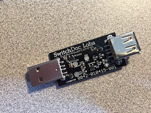 USB PowerControl
Step 3: Turning Your Raspberry Pi on and Off Safely


Safely Turning the Pi On and Off
The Brownout Problem
In this important step, we are going to discuss the problem of powering down and up your Raspberry Pi. In Solar Powered systems, this is called the "Brownout Problem". We will be showing how to use a simple device, the USB Power Control from SwitchDoc Labs to solve this problem.
One of the most important issue in designing a Raspberry Pi Solar Power System is turning on and off. The "Brownout Problem" is a real issue. Why worry? If you have a long string of cloudy days, you may run your battery down. You can compensate for this in your design by adding more panels and more batteries, but that can get really expensive and your system might still run out of power, just a lot less frequently.
Shutting Off the Pi
Shutting a Raspberry Pi off is pretty easy. When the battery voltage falls below some value, you just do a “sudo shutdown -h now” and your Raspberry Pi will shutdown cleanly. After doing the test talked about here ( http://www.switchdoc.com/2015/04/turning-the-pi-on-and-off-weatherpi-solar-power/ ) , we chose 3.5V as the voltage to shut down the Raspberry Pi.
Note that in most solar power systems, you need to monitor the battery voltage and not the 5V power supply because with most modern voltage booster systems, the circuitry will work very hard to keep the 5V going and then just give up crashing to a much lower voltage when it runs out of power.
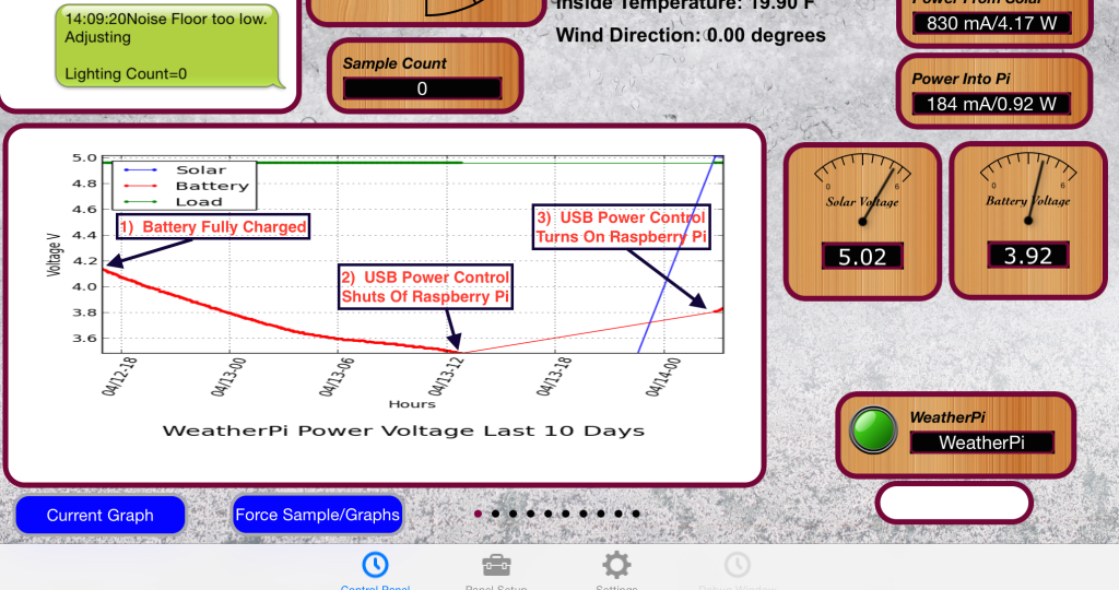 Showing Shutdown Voltage and Startup Voltage on the Raspberry Pi
That means your computer would have little or no warning when the voltage is about to drop. By monitoring the battery voltage, you can tell when the battery is getting low enough and then shut down your computer safely. For LiPo batteries, this will be when your voltage gets down to about 3.5V or so. This can all be monitored with the SunAirPlus solar charge controller that we are using in GroveWeatherPi.
Starting the Pi
Enough about shutting down the computer. What about starting it up?
The Issue
You can’t just let the controller power up the computer. The problem is that the supply voltage will move up and down until there is enough charge in the battery to fully supply the computer. When the computer turns on (connecting a full load), you will pull the battery down hard enough to brown out the computer causing the Raspberry Pi to crash. This constant rebooting cycle can corrupt and ruin your SD card and cause your computer to never boot at all, even when the power is restored. We had this VERY thing happen to us 3500 miles away with Project Curacao. Arduinos are more tolerant of this, but Raspberry Pi’s do not like a ill-behaved power supply. You just can’t be sure of what state the computer will power up at without a good power supply.
This issue can be handled in a number of ways. The first is to use another computer (like an Arduino made to be very reliable by using a WatchDog - see the Reliable Computer series on switchdoc.com - http://www.switchdoc.com/2014/11/reliable-projects-watchdog-timers-raspberry-pi-arduinos/ ) to disconnect the Raspberry Pi’s power through a latching relay or MOSFET when there isn’t enough power. Project Curacao ( http://www.switchdoc.com/project-curacao-introduction-part-1/) used this approach.
We didn't want to add an additional computer to GroveWeatherPi, so we chose a second solution.
Power Your Pi Up and Down with the USB Power Control
A second (and cheaper!) way of handling the brownout and power up problem is to use a dedicated power controller that will shut the power off to the Raspberry Pi and restore the power when the battery voltage is high enough to avoid ratcheting the supply voltage up and down because of the load of the Raspberry Pi. This is called Hysteresis. We have designed a board to do just this (called the USB Power Controller) that will plug between the USB coming out of the SunAir Solar Power Controller and the Raspberry Pi as in the picture to the below.
[caption id="attachment_13452" align="aligncenter" width="930"] SunAIrPlus Plugged into the USB Power Control Board[/caption]
The USB Power Controller Board
The USB PowerControl board is a USB to USB solid state relay.
Anything you can plug into a USB port can be controlled with USB PowerControl. It's easy to hook up. You connect a control line (a GPIO line or the output of a LiPo battery) to the LIPOBATIN line on the USB Power Control device and if the line is LOW (< ~3.3V) the USB Port is off. If it is HIGH (above 3.8V) the USB Port is turned on and you have 5V of power to the USB plug.
There is a hysteresis circuit so the board won't turn on and then turn immediately off because the power supply is yanked down when the computer turns on (putting a load not the battery).
There is little software for this device. You connect it directly to your LiPo battery for automatic control! The only software used detects the battery voltage and decides when to shut down the computer. The USB Power Control takes care of shutting the power to the Raspberry Pi when the battery voltage gets low enough. Note that a shutdown Raspberry Pi still draws current (according to one quick measurement, about 100ma).
One More Scenario
One last point. After thinking about the power down sequence, we came up with one more scenario. What if:
- The battery voltage reaches 3.5V and the Raspberry Pi is shut down.
2. The USB PowerController will turn the power off when the battery reaches about ~3.4V.
However, what if the sun comes up at this time and the battery starts charging again?
Then the USB PowerController will never reach ~3.4V and will never turn off. And the Pi will never reboot. Not a good scenario!
We fixed this problem by adding a hardware watchdog timer.
For a tutorial on hardware watchdog timers, read the SwitchDoc series starting here. http://www.switchdoc.com/2014/11/reliable-projects-watchdog-timers-raspberry-pi-arduinos/
We used a Dual WatchDog Timer Board to fix this problem. We set the RaspberryPi python to "pat the dog" (preventing the watchdog timer from triggering) every 10 seconds. The timer is set to trigger after about 200 seconds if it isn't patted. The timer is connected to pull the "COut" point down to ground on the USB PowerController which shuts off the Raspberry Pi.
SOLDERING NOTE: If you choose to add the USB PowerControl you will need to solder a single wire to the COut Test Point. The next version of the USB PowerControl will have two Grove connectors to eliminate this wire.
Because of the hysteresis circuit on the USB PowerController the Raspberry Pi will stay off until the battery voltage reaches ~3.9V and then the Pi will reboot. Now the above scenario will never happen. By the way, there is no real way of using the internal Pi Watchdog to do this. You don't want to reboot the Pi, you want to shut off the power in this scenario.
If you don't want to solder the one wire required (which will be replaced with a jumper pin and Grove connector in the next version of the USB PowerControl board), you may leave this board out. You may have to go out and hand reset your solar power station when the above scenario occurs, but hopefully not too often.
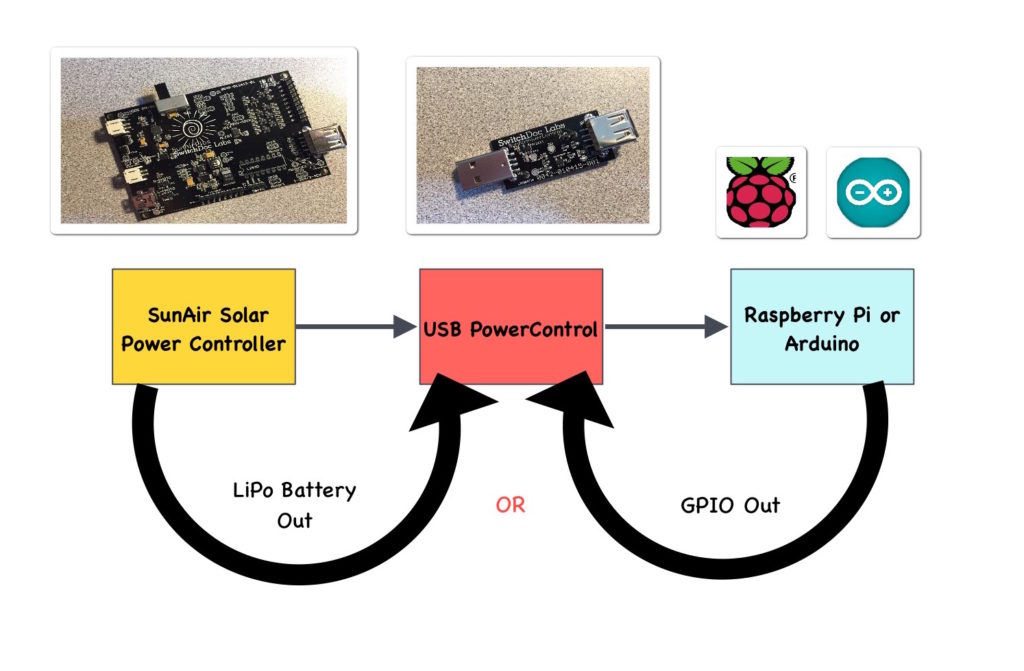 Block diagram of USB/SunAirPlus
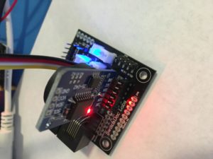
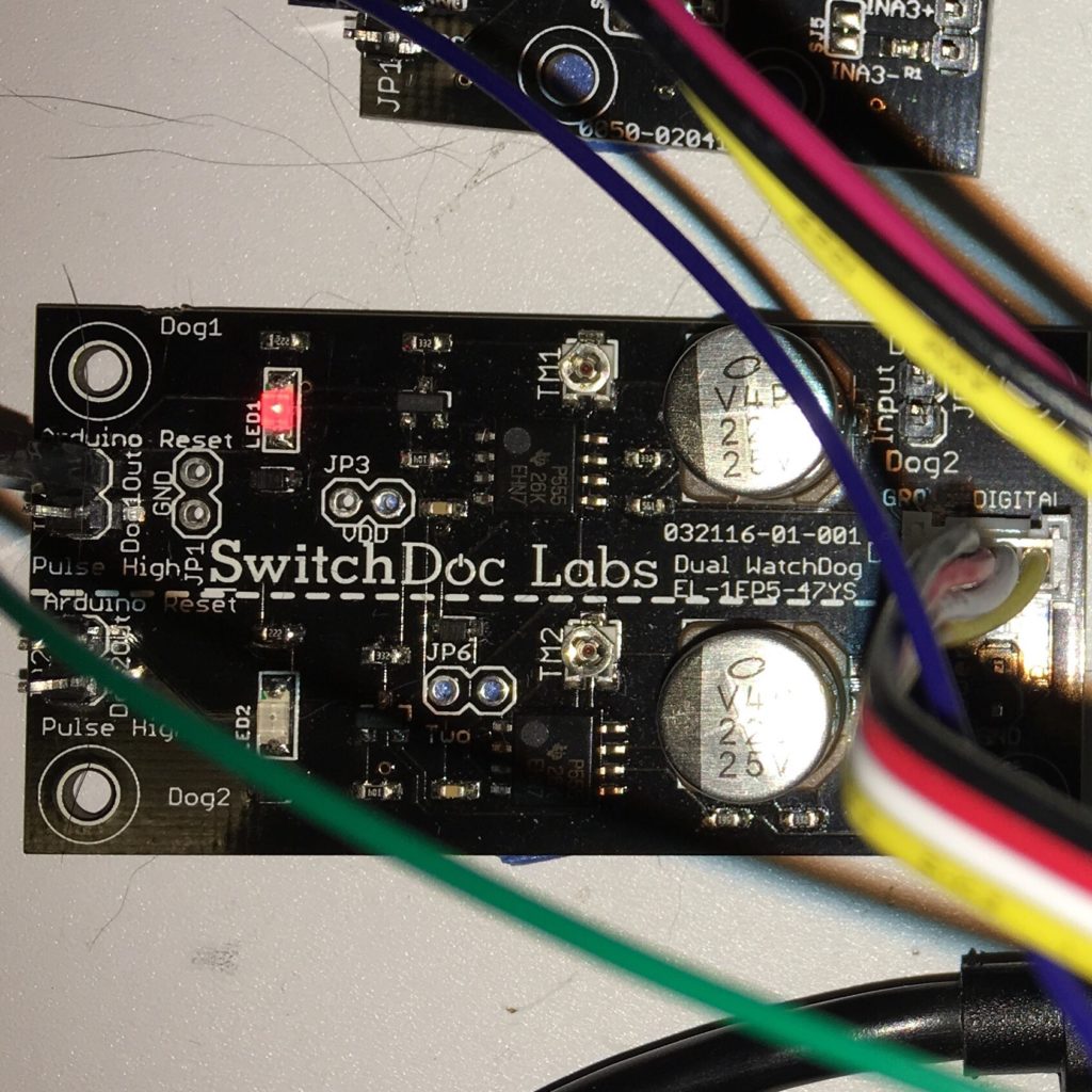 Dual WatchDog Timer
Step 4: The Parts List for the GroveWeatherPi

The Parts List for GroveWeatherPi
No project is complete without a parts list. These are suggestions! There are lots of options for a number of these boards. If you substitute, make sure you check for compatibility!
| Parts List for GroveWeatherPi - Raspberry Pi A+ or PiZero with Pi2Grover and Lightning Detector | ||||
| Part Number | Part Description | Source | Included in GroveWeatherPi Product Bundle | Included In GroveWeatherPi Solar Add-on Product Bundle |
| Raspberry Pi | Raspberry PI A+ or PiZero | Multiple | ||
| Pi2Grover | Raspberry Pi to Grove Interface | www.switchdoc.com amazon.com | X | |
| Grove Weather Board | Weather Instrument and Grove Interface (includes DS3231 RTC) | www.switchdoc.com amazon.com | X | |
| WeatherRack | Weather Instruments - Wind Speed, Rain, Wind Vane | store.switchdoc.com www.argentdata.com www.sparkfun.com amazon.com | X | |
| Grove I2C 4Ch/16Bit ADC | 4 channel 16 bit I2C Analog to Digital Converter | store.switchdoc.com amazon.com | X | |
| Grove OLED 64x128 I2C Display | OLED display for Weather Station | store.switchdoc.com www.seeedstudio.com amazon.com | X | |
| HUT21D-F Inside Temperature / Humidity Sensor | Optional Inside Temperature and Humidity Sensor (Requires Soldering - Optional) | www.adafruit.com | X | |
| Grove to Grove Connector Cables (6) | For connecting from Grove to Grove Connectors | store.switchdoc.com amazon.com | X | |
| Long Grove to Grove Connector Cables (2) | 50cm Cables for Grove to Grove Connectors For I2C Detector | store.switchdoc.com amazon.com | X | |
| JST-PH Extender for Solar Panel JST-PH 2 Plug | Extender Plug for Solar Panels | https://www.adafruit.com/products/1131 | X | |
| Solar Panels | 330mA/6V - Two | store.switchdoc.com | X (3 included!) | |
| Larger Solar Panels | 550mA and up | voltaicsystems.com | ||
| BUD NEMA Box | 10 - 23/32â, 6-25/32â, 4-21/64â Weather Proof Box | http://amzn.to/2bdNufd | ||
| Raspberry Pi A+/WiFi USB Dongle | Raspberry Pi Compatible WiFi Dongle | Multiple Sources | ||
| Grove I2C 4 Channel Mux | 4 Channel I2C Multiplexer | store.switchdoc.com amazon.com | X | |
| USB PowerControl | USB Power Switch | store.switchdoc.com amazon.com | X | |
| Grove SunAirPlus | Solar Power Controller/Charger and Data Collector | store.switchdoc.com amazon.com | X | |
| USB cable - A/MicroB | Plug between SunAirPlus and Raspberry PI | https://www.adafruit.com/products/592 store.switchdoc.com | X | |
| Grove Dual External WatchDog Timer | External Hardware WatchDog Timer | store.switchdoc.com amazon.com | X | |
| Grove Lightning Detector - MOD-1016G | I2C Lightning Detector | store.switchdoc.com amazon.com embeddedadventures.com | X | |
| DS3231 RTC | DS3231 Real Time Clock (included with the Grove Weather Board above) | store.switchdoc.com amazon.com | X | |
| Grove AM2315 Outdoor Temperature/Humidity Sensor | Encased I2C Accurate Temperature/Humidity Sensor | store.switchdoc.com amazon.com | X | |
| BMP280 Barometric Pressure / Temperature Sensor | Included with the Grove Weather Board above | X | ||
| PKCELL Lithium Ion (LiPo) Battery Pack - 3.7V 6600mAh | Battery for SunAirPlus | www.adafruit.com | ||
| I2C 4 Port Passive Hub | 4 port hub - no active electronics | store.switchdoc.com amazon.com | X | |
| 8 Female to Female Jumper Plugs | 6 Inch long jumper wires | Multiple Sources | ||
| 1 Female to Female Long Jumper Plug | 12 inch long jumper wire | Multiple Sources | ||
| Hookup WIre | Multiple Sources | |||
| Silicon Caulking for Sealing Holes | Multiple Sources | |||
| Velcro for attaching Boards to NEMA Box | Multiple Sources | |||
| Screws and Bolts for attaching the 3D Printed Parts | Multiple Sources | |||
GroveWeatherPi Discounted Part Bundles Available from SwitchDoc Labs
For convenience, we have bundled the parts that we produce or have good sources for and have these bundles available for sale on store.switchdoc.com
GroveWeatherPi Product Bundle 0300-GWPMIX-DSBT
GroveWeatherPi Solar Add-on Product Bundle 0302-SOLARGWPMIX-DSBT
Step 5: The Wiring List for the GroveWeatherPi


The Wiring List
 Fully Wired GroveWeatherPi
Here is where we install all of the Grove cables, the 7 jumper wires and the one optional jumper cable to a SOLDERED joint on the USB Power Control Board.
| Wiring List for Raspberry Pi GroveWeatherPi System | ||
| From | To | Description |
| Pi2Grover / D13/D16 | MOD-1016G / Grove IRQ | 50cm Grove Cable |
| Pi2Grover / D21/D26 | Weather Board / Grove D Rain Bucket | Grove Cable |
| Pi2Grover / D26 | Weather Board / Grove D Anemometer | Grove Cable |
| Pi2Grover / Grove I2C | 4 Chan I2C Mux / Grove J1 - Computer I2C | Grove Cable |
| 4 Chan I2C Mux / Grove J2 / Bus0 | 4 Slot I2C Expander / Any Slot | Grove Cable |
| 4 Chan I2C Mux / Grove J3 / Bus1 | MOD-1016 / Grove I2C | 50cm Grove Cable |
| 4 Chan I2C Mux / Pin Header JP7-1 | 4 Chan I2C Mux / Pin Header JP6-1 | Set Power of I2C Bus to VDD |
| 4 Chan I2C Mux / Pin Header JP7-2 | 4 Chan I2C Mux / Pin Header JP6-2 | Set Power of I2C Bus to VDD |
| 4 Chan I2C Mux / Pin Header JP7-3 | 4 Chan I2C Mux / Pin Header JP6-3 | Set Power of I2C Bus to VDD |
| 4 Chan I2C Mux / Pin Header JP7-4 | 4 Chan I2C Mux / Pin Header JP6-4 | Set Power of I2C Bus to VDD |
| 4 Slot I2C Expander / Any Slot | OLED Display / Grove I2C | Grove Cable |
| 4 Slot I2C Expander / Any Slot | Grove 4Ch/16Bit ADC / Grove I2C | Grove Cable |
| 4 Slot I2C Expander / Any Slot | Weather Board / Grove I2C | Grove Cable |
| Grove 4Ch/16Bit ADC / Grove A1 | Weather Board / Grove A Wind Vane | Grove Cable |
| Weather Board / Grove I2C | Grove AM2315 Temperature / Humidity Sensor | Grove Cable |
| (Optional) HTU21D-F Inside Temperature / Humidity Sensor | Weather Board / JP14 Plug in | Plug in Board |
| Weather Board RJ11 - Rain Bucket | WeatherRack Rain Bucket Plug | RJ11 Cable |
| Weather Board RJ11 - Anemometer / Wind Vane | WeatherRack Anemometer / Wind Vane Plug | RJ11 Cable |
Note: You will use the Female Pin Header to Grove Connector cable provided with your SunAirPlus board in this section.
| Wiring List for Solar Power Subsystem for the Raspberry Pi GroveWeatherPi System | ||
| From | To | Description |
| Raspberry Pi Power Micro USB | USB PowerControl USB Out | Uses USB cable - A/MicroB |
| USB PowerControl USB In | SunAirPlus 5V USB Power Out | |
| USB PowerControl LIPOBATIN | SunAirPlus JP4 Battery Out | Female to Female Header Jumper Wire |
| SunAirPlus - From Computer / SCL | Yellow Female Header Pin on Grove Connector | SCL |
| SunAirPlus - From Computer / SCL | White Female Header Pin on Grove Connector | SDA |
| SunAirPlus - From Computer / SCL | Red Female Header Pin on Grove Connector | VDD |
| SunAirPlus - From Computer / SCL | Black Female Header Pin on Grove Connector | GND |
| Grove Connector (Previous 4 Items) | 4 Chan I2C Mux / Grove J4 - Bus 2 | Female Pin Header to Grove Connector |
| SunAIrPlus Battery Female Plug | LiPo Battery JST-2 Plug | |
| SunAIrPlus Solar Panel Female Plug | Solar Panel JST-2 Plug - Note: If you have two solar panels, you will need to solder + to + and - to - on the back of the solar panels. A VoltaicSystems Solar Panel will require an adaptor plug | |
| Wiring List for WatchDog Board for the Raspberry Pi GroveWeatherPi System (optional) | ||
| From | To | Description |
| WatchDog Board JP5/VDD | Raspberry Pi GPIO Header Pin 1/3.3V | Female to Female Jumper Wire |
| WatchDog Board JP5/GND | Raspberry Pi GPIO Header Pin 6/GND | Female to Female Jumper Wire |
| WatchDog Board JP7/Dog1 | Raspberry Pi GPIO Header Pin 11/GPIO17 | Female to Female Jumper Wire |
| WatchDog Board JP4/ArduinoReset | USB PowerControl TP3/COUT - Soldered To Pad (DO NOT CONNECT THIS WIRE UNITL YOU ARE DONE TESTING AND MODIFYING THE SOFTWARE!) | Cut one end of 12 inch Female to Female Header Jumper Wire and solder it to TP3/COUT pad as shown below in Step 7. |
Note: If you are using a Voltaic Systems Solar Panel and you don’t want to solder your own plug, you need the following adaptors:
Female JST PH 2 Pin to Female 2.1mmx5.5mm Jack http://www.mcmelectronics.com/product/29-6380
Male 2.1mmx5.5mm to Male 2.1x5.5mm http://www.ebay.com/itm/5-5mm-x-2-1mm-Male-Plug-to-5-5mmx2-1mm-Male-CCTV-DC-Power-Plug-Adapter-Connector-/300689722442?hash=item4602810c4a:g:5m4AAOSwpDdVNdbs
Female 2.1mmx5.5mm to Female 21.1mmx3.5mm Adaptor http://www.voltaicsystems.com/f5521-f3511
DS3231 Real Time Clock
Plug the included DS3231 Real Time Clock into the provided socket on the Weather Board. Align the GND pins! The battery faces the inside of the board and the LED side faces the outside of the board.
Now before you power anything on, go back and check every connection!
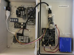
Step 6: Building the Box

Building the Box
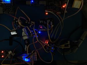
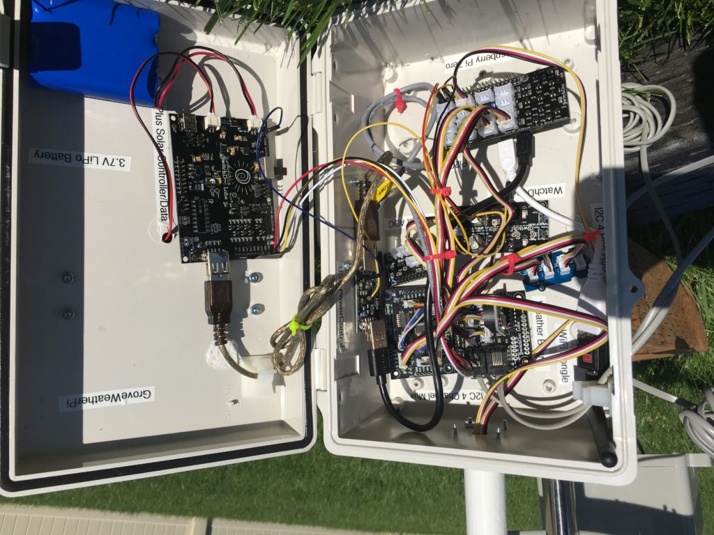
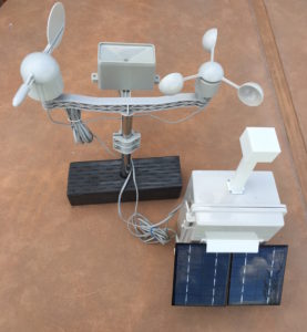
As with most projects, we tend to "breadboard" the circuitry before we put it into the enclosure. With GroveWeatherPi, we spread out the parts, wired them up, made sure each of the major paths worked (and of course, took the obligatory nighttime geek shot) and then started placing them in the box, attaching them velcro to the sides, bottom and top of the box.
Once you have it breadboarded you can run the following test.
On your Raspberry Pi install the github archive github.com/switchdoclabs/SDL_Pi_GroveWeatherPi .
Do the following:cd SDL_Pi_GroveWeatherPi
cd SDL_Pi_TCA9545
sudo python testSDL_Pi_TCA9545.py
Test SDL_Pi_TCA9545 Version 1.0 - SwitchDoc Labs
Sample uses 0x73
Program Started at:2016-08-13 18:52:00
-----------BUS 0-------------------
tca9545 control register B3-B0 = 0x1
ignore Interrupts if INT3' - INT0' not connected
tca9545 control register Interrupts = 0x0
0 1 2 3 4 5 6 7 8 9 a b c d e f
00: -- -- -- -- -- -- -- -- -- -- -- -- --
10: -- -- -- -- -- -- -- -- -- -- -- -- -- -- -- --
20: -- -- -- -- -- -- -- -- -- -- -- -- -- -- -- --
30: -- -- -- -- -- -- -- -- -- -- -- -- 3c -- -- --
40: 40 -- -- -- -- -- -- -- 48 -- -- -- -- -- -- --
50: -- -- -- -- -- -- -- 57 -- -- -- -- -- -- -- --
60: -- -- -- -- -- -- -- -- 68 -- -- -- -- -- -- --
70: -- -- -- 73 -- -- -- 77
-----------------------------------
-----------BUS 1-------------------
tca9545 control register B3-B0 = 0x2
ignore Interrupts if INT3' - INT0' not connected
tca9545 control register Interrupts = 0x0
0 1 2 3 4 5 6 7 8 9 a b c d e f
00: 03 -- -- -- -- -- -- -- -- -- -- -- --
10: -- -- -- -- -- -- -- -- -- -- -- -- -- -- -- --
20: -- -- -- -- -- -- -- -- -- -- -- -- -- -- -- --
30: -- -- -- -- -- -- -- -- -- -- -- -- -- -- -- --
40: -- -- -- -- -- -- -- -- -- -- -- -- -- -- -- --
50: -- -- -- -- -- -- -- -- -- -- -- -- -- -- -- --
60: -- -- -- -- -- -- -- -- -- -- -- -- -- -- -- --
70: -- -- -- 73 -- -- -- --
-----------------------------------
-----------BUS 2-------------------
tca9545 control register B3-B0 = 0x4
ignore Interrupts if INT3' - INT0' not connected
tca9545 control register Interrupts = 0x0
0 1 2 3 4 5 6 7 8 9 a b c d e f
00: -- -- -- -- -- -- -- -- -- -- -- -- --
10: -- -- -- -- -- -- -- -- -- -- -- -- -- -- -- --
20: -- -- -- -- -- -- -- -- -- -- -- -- -- -- -- --
30: -- -- -- -- -- -- -- -- -- -- -- -- -- -- -- --
40: 40 -- -- -- -- -- -- -- 48 -- -- -- -- -- -- --
50: -- -- -- -- -- -- -- -- -- -- -- -- -- -- -- --
60: -- -- -- -- -- -- -- -- -- -- -- -- -- -- -- --
70: -- -- -- 73 -- -- -- --
-----------------------------------
-----------BUS 3-------------------
tca9545 control register B3-B0 = 0x8
ignore Interrupts if INT3' - INT0' not connected
tca9545 control register Interrupts = 0x0
0 1 2 3 4 5 6 7 8 9 a b c d e f
00: -- -- -- -- -- -- -- -- -- -- -- -- --
10: -- -- -- -- -- -- -- -- -- -- -- -- -- -- -- --
20: -- -- -- -- -- -- -- -- -- -- -- -- -- -- -- --
30: -- -- -- -- -- -- -- -- -- -- -- -- -- -- -- --
40: -- -- -- -- -- -- -- -- -- -- -- -- -- -- -- --
50: -- -- -- -- -- -- -- -- -- -- -- -- -- -- -- --
60: -- -- -- -- -- -- -- -- -- -- -- -- -- -- -- --
70: -- -- -- 73 -- -- -- --
-----------------------------------
If your display matches the above, you have correctly wired your GroveWeatherPi. If some devices are missing, look up the devices above in the I2C Address chart and check their wiring. Always shut down and turn your Raspberry Pi off before changing wiring.
Putting the GroveWeatherPi into the BUD Industries box is pretty straight forward. We chose to put the solar power part of the circuit on top and the Raspberry Pi and the WeatherPiArduino Sensor array in the box bottom. The parts were all placed and then all the screw holes and outside screws were sealed with silicon caulking.
Step 7: The Hardware WatchDog Timer


Optional Section - Dual WatchDog Timer
The addition of the external watchdog timer improves the reliability of your solar powered weather station by removing the scenario talked about in the Watchdog section earlier in this chapter. To add this board, one wire must be soldered on the TP3 (COut) on the USB Power Control part as shown below. This wire is connected to a female jumper header that connects to the DOG1_ARDUINORESET (unfortunately named) on the Dual WatchDog Timer.
FYI, the next version of the USB PowerControl Board will add pins to both of the TP pads so even that soldering part is going away!
]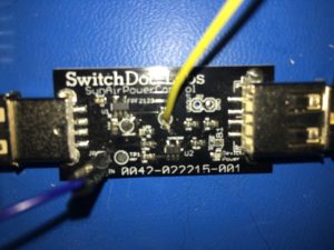 USB Power Control with Wire soldered to TP3
Setting the WatchDog Timer Length
To get your WatchDog timer to wait for 240 seconds before rebooting you must take a small screwdriver and set the timeout internal on the board.
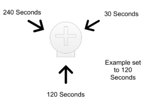 Timer Interval Setting Potentiometer
The timeout interval for each WatchDog timer is set by turning the TM1 single turn potentiometer. It can be set from 30 seconds to 240 seconds. It is set by turning it over a 270 degree range. Turn the small screw to face the 240 second mark in the above figure.
We used strong Velcro with adhesive to mount the parts in the box.
Make sure you place the battery toward the bottom as it is heavy and the heat of the summer could make it come loose.
Step 8: 3D Printed Parts for GroveWeatherPi


3D Printed Parts
One of the big changes in the way people build prototypes is the availability of inexpensive 3D Printers. It used to be difficult to build prototype cases and stands for various electronic projects. Now it is easy to design a case in one of many types of 3D software and then print it out using your 3D Printer. For the GroveWeatherPi, we used OpenSCAD ( http://www.openscad.org ) to do the design. OpenSCAD is a free 3D CAD system that appeals to programmers. Rather than doing the entire design in a graphical environment, you write code (consisting of various objects, joined together or subtracted from each other) that you then compile in the environment to form a design in 3D space.
We have three 3D Printed Parts. These can be ordered from store.switchdoc.com if you don’t wish to build your own.
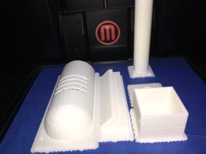 GroveWeatherPi 3D Print Complete
Solar Panel Mount
The Solar Panel Mount is attached via 4 screws to the door of the BUD enclosure. The solar panels are then slid into the slot at the top, holding the panels at a 45 degree angle which is optimal for the latitude at SwitchDoc Labs. If you are building GroveWeatherPi elsewhere in the world, you may want to adjust it to match your latitude. We are currently rethinking this friction fit bracket. It loosens up in the hot sun and we had to apply some glue to make sure it will stay connected.
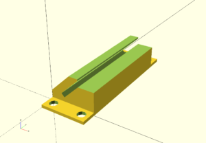 Solar Panel Mount
//
// WXPi Solar System
//
// SwitchDoc Labs - 08/08/2016
//
//
// WXLink outside Solar
//


include
include


difference()
{
    union()
    {
cube([30,70,30]);
        translate([0,-10,0])
        cube([30,90,2]);
    }


rotate([0,45,0])
translate([0,-5,10])
    cube([3,90,40]);

    translate([-5,-5,20])
    cube([40,80,30]);

    rotate([0,45,0])
translate([-15,-5,5])
    #cube([10,90,40]);

    translate([19,-5,15])
    #cube([15,90,6]);

    // screw holes
    translate([5,-5,-10])
    #cylinder(h=15, r=2.8);

        // screw holes
    translate([25,-5,-10])
    #cylinder(h=15, r=2.8);


        // screw holes
    translate([5,75,-10])
    #cylinder(h=15, r=2.8);

        // screw holes
    translate([25,75,-10])
    #cylinder(h=15, r=2.8);

}
Radiation and Water Shield for AM2315 Outdoor Temperature/Humidity Sensor
The AM2315 is encased, but not totally water proof. It needs to be protected from direct rain and also from direct sun. If the device is in the direct sun, then the temperature will read too high and eventually the humidity sensor on the AM2315 will die. The jury is still out whether we need to put a sun shade above the radiation shield.
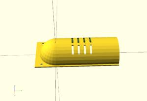 Radiation and Water Shield
//
//GroveWeatherPi Solar System
//
// SwitchDoc Labs - 04/01/15
//
//
//GroveWeatherPi AM2315 Outdoor temp cover
//


include
include


module Tube()
{

       // tube


    difference()
    {


   //     cylinder(h=130, r=28);
        cylinder(h=130, r=28);

        translate([0,0,-2])
        cylinder(h=132, r=26);

        translate([-30,-90,-2])
        #cube([231,90,135]);


          // vents

        translate([-20,100,100])
        rotate(90,[1,0,0])
        #cube([40,3,200]);

        translate([-20,100,90])
        rotate(90,[1,0,0])
        #cube([40,3,200]);

        translate([-20,100,80])
        rotate(90,[1,0,0])
        #cube([40,3,200]);

        translate([-20,100,70])
        rotate(90,[1,0,0])
        #cube([40,3,200]);

    }

}


module OutdoorCover()
{


    // sphere

    difference()
    {
        sphere(r=28);

        sphere(r=25);

        translate([-45,0,0])
        #cube([90,90, 100]);

        translate([-45,-45,-100])
        #cube([90,90, 100]);


    }

    // tube

    translate([0,130,0])
    rotate(90,[1,0,0])
    Tube();

    // mounting plates

    difference()
    {
        translate([-30,-35,0])
        cube([60,165,2]);


        translate([-20,-15,0])
        cube([40,145,2]);

        // screw holes

        translate([25,-24,-2])
        #cylinder(r=2,h=15);

        translate([-25,-24,-2])
        #cylinder(r=2,h=15);


    }

}


difference()
{

OutdoorCover();

      translate([-50,105,-10])
  #cube([100,100,100]);

}
Lightning Detector Pylon
The lighting detector pylon is to move the very sensitive MOD-1016G Lightning Detector away from the noisy electronics within the GroveWeatherPi. We noticed early on that we were getting a lot of spurious lightning detection from the device. Moving it about 30cm from the electronics in a separate pylon fixed that problem.
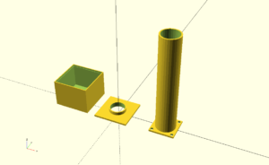 Lightning Detector Pylon
//
// WeatherPi Lightning Sensor Block Extension
//
// SwitchDoc Labs 5/18/15
//
//

module sensorPylon()
{

    // tube

    difference()
    {
        union()
        {
            cylinder(120, r=12);

           // flanges

            translate([-15,-15,0])
            cube([30,30,2]);
        }

        translate([0,0,-10])
        cylinder(150, r=10.5);

        // screw holes
        translate([-12,-12,-5])
        #cylinder(h=10,r=2.0,$fs=6);

         translate([-12,12,-5])
        #cylinder(h=10,r=2.0,$fs=6);

         translate([12,12,-5])
        #cylinder(h=10,r=2.0,$fs=6);

         translate([12,-12,-5])
        #cylinder(h=10,r=2.0,$fs=6);

    }


}

module sensorBox()
{

    difference()
    {
        translate([-16.5,-16.5,0])
        cube([43,43,33]);

        translate([-15,-15,-2])
        cube([40,40,32]);

        translate([-15.5,-15.5,-1])
        cube([41,41,3]);

    }


}

module sensorPlatform()
{

    difference()
    {
        union()
        {
            translate([-17.95,-17.95,-1])
            cube([40.9,40.9,2]);

            translate([2.5,2.5,-5])
            #cylinder(5,r=10.4);
        }

        translate([2.5,2.5,-5])
        #cylinder(10,r=9.0);
    }


}

/*
sensorPylon();

translate([0,0,180])
sensorBox();

translate([0,0,160])
sensorPlatform();
*/

translate([60,0,0])
sensorPylon();

rotate(180,[0,1,0])
{
translate([50,0,-33])
sensorBox();

translate([0,0,-1])
sensorPlatform();
}
Step 9: Mounting the Outside Parts on the Box


Mounting the AM2315 and Radiation Shield
Drill a hole on the right side (wihtout the clips) of the BUD enclosure and route the Grove plug on the AM2315 inside to the hardware. Using the mounting hardware clip provided, screw the clip down to the base. Clip the sensor into place. Then place the radiation shield over the sensor and screw it down to the BUD enclosure. Note: After some consideration and experience, it might be better to mount this on the bottom of the box to keep the whole assembly and the radiation shield out of the direct sunlight.
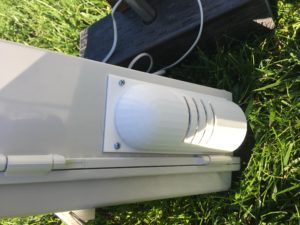 Mounted Radiation Shield
Mounting the Solar Panels
Mount the Solar Panel Bracket on to the door of the BUD enclosure and attach it with four screws and bolts to the enclosure. Drill a hole in the door to route the cables with the JST connector into the box.
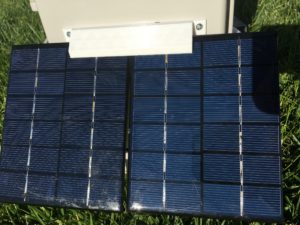 Mounted Solar Panels
Mounting the Lightning Detector
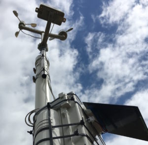
Drill a hole for the Grove connectors in the top side of the BUD enclosure. Screw the Pylong down, route the wires up through the hole and then place the pylon top onto the pylon. Secure the wired MOD-1016G on the pylon platform and then snap the top box onto the assembly.
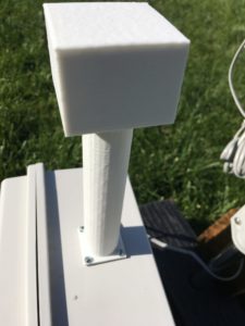 Mounted Lightning Detector Pylon
The Last Things to Build
Three things:
- Condensation hole. At the lowest part of the box (and what the lowest part is depends on how you are mounting the box!) cut a small hole (1/2 inch should do it), cover it with screen (to keep the wasps out).
- The Pi 2 Grover has a very, very strong physical connection to the Pi and will not come loose. The Grove cables have a good strong physical connection too, and you can use buckled connectors if you want. We do recommend putting a small dot of silicon caulking on the singe wire jumpers to make sure they don't pull free in a storm. If you don't feel velcro will be strong enough, then use standoff posts and screws to secure all the boards. They all have mounting holes.
- After you have verified everything is working, seal all the holes and screws with silicon caulking and be liberal about it. Caulk the pylon base, the top and the bottom to make sure they won’t leak.
Step 10: The GroveWeatherPi Python Software for the Raspberry Pi

The Raspberry Pi Python Software
A big part of the GroveWeatherPi project is the software. All of the python software for this project is up on github at the switchdoclabs section ( github.com/switchdoclabs/SDL_Pi_GroveWeatherPi ). We also included all of the various libraries for the I2C devices we are using.
Non-Normal Requirements for your Pi
You will need to add the following software and libraries to your Raspberry Pi
MySQL
There are lots of tutorials on the net for installing MySQL. Here is the one we used ( http://raspberrywebserver.com/sql-databases/using-mysql-on-a-raspberry-pi.html ). Remember to use MySQL to set up the GroveWeatherPi Database as shown in the README.md
MatPlotLib
This is the graphing subsystem with a great interface to Python. It is a bit more complex to install, so we wrote a tutorial on how to install it on SwitchDoc.com ( http://www.switchdoc.com/2014/01/matplotlib-raspberry-pi-mysql-and-project-curacao/ ). Note that the installation takes a long time, about 8 hours on a Raspberry Pi B+ (mostly unattended).
The GroveWeatherPi Python Software
The GroveWeatherPi software is pretty simple. The application was much less complex than the Project Curacao software( http://www.switchdoc.com/project-curacao-software-system-part-6/ ) so we decided not use the apscheduler package and decided just to use a simple loop with a "every 15 seconds" type of control.
Here is the main loop:secondCount = 1
while True:
# process Interrupts from Lightning
if (as3935Interrupt == True):
try:
process_as3935_interrupt()
except:
print "exception - as3935 I2C did not work"
if (config.TCA9545_I2CMux_Present):
tca9545.write_control_register(TCA9545_CONFIG_BUS0)
# process commands from RasPiConnect
print "---------------------------------------- "
processCommand()
if ((secondCount % 10) == 0):
# print every 10 seconds
sampleAndDisplay()
patTheDog() # reset the WatchDog Timer
blinkSunAirLED2X(2)
# every 5 minutes, push data to mysql and check for shutdown
if ((secondCount % (5*60)) == 0):
# print every 300 seconds
sampleWeather()
sampleSunAirPlus()
writeWeatherRecord()
writePowerRecord()
if (batteryVoltage < 3.5): print "--->>>>Time to Shutdown<<<<---"
shutdownPi("low voltage shutdown")
# every 15 minutes, build new graphs
if ((secondCount % (15*60)) == 0):
# print every 900 seconds
sampleWeather()
sampleSunAirPlus()
doAllGraphs.doAllGraphs()
# every 30 minutes, check wifi connections
if ((secondCount % (30*60)) == 0):
# print every 900 seconds
WLAN_check()
#WLAN_check()
# every 48 hours, reboot
if ((secondCount % (60*60*48)) == 0):
# reboot every 48() hours seconds
rebootPi("48 hour reboot")
secondCount = secondCount + 1
# reset secondCount to prevent overflow forever
if (secondCount == 1000001):
secondCount = 1
time.sleep(1.0)
Note that we reboot the Pi every two days. Why do we do that? We have noticed that after heavy usage of MatPlotLib and/or MySQL, that sometimes after a long time, you run out of resources, giving all sorts of odd behavior. Since the RaspberryPi A+ or the Zero has a small amount of RAM, rebooting is the easiest way of fixing it.
Check out all the code up on github.com ( github.com/switchdoclabs/SDL_Pi_GroveWeatherPi ).
Step 11: Latest Software and Hardware Improvements


Hardware Improvements
The version 2.8 release of GroveWeatherPi.py contains additional support for new hardware and a number of different improvements in the software.Addition of Grove HDC1080 Support
The original GroveWeatherPi design used a HTU21D-F for sensing inside the box temperature and humidity. It was an expensive device and required soldering. We have now developed and inexpensive Grov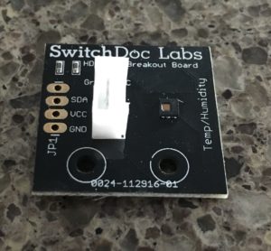 e based temperature and humidity device based on the I2C HDC1080 IC and you can find the device and documentation here.
 The HDC1080 is a HDC1000 compatible temperature and humidity sensor. It is located at I2C address 0x40.
Grove - Temperature and Humidity Sensor (HDC1080) utilizes a HDC1080 sensor, from Texas Instruments. It is a digital humidity sensor with integrated temperature sensor that provides excellent measurement accuracy at very low power. The device measures humidity based on a novel capacitive sensor. The humidity and temperature sensors are factory calibrated. The innovative WLCSP (Wafer Level Chip Scale Package) simplifies board design with the use of an ultra-compact package. The HDC1080 is functional within the full –40°C to +125°C temperature range, and 0-100% RH range.
The HDC1080 driver software is also pure Python rather than a C based program called by a Python system call.
You can buy this product on the SwitchDoc Labs store.
Features
• - Grove connector compatible • - I2C Interface• - Low Power• - Wide operating voltage rangeSpecifications
• - Supply Voltage: 3~5Vdc;• - Working Current: 0.12~90uA;• - Relative humidity accuracy: ±3%RH;• - Relative humidity operating range: 0~100%RH;• - Temperature accuracy: ±0.2℃;• - Temperature range: -40~125℃;• - Operating temperature: -20~85℃• - Dimensions: 40×20mm.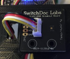
SunLight Sensor Support
GroveWeatherPi now supports the SI1145 Sunlight / IR / UVIndex I2C Grove sensor. The Grove Sunlight, IR and UV I2C sensor can monitor sunlight intensity, IR intensity and UV intensity. All in one sensor. The sensor is a multi-channel digital light sensor, which has the ability to detect UV-light, visible light and infrared light. This device is based on SI1145, a new sensor from SiLabs. The Si1145 is a low-power, reflectance-based, infrared proximity, UV index and ambient light sensor with I2C digital interface and programmable-event interrupt output. This device offers excellent performance under a wide dynamic range and a variety of light sources including direct sunlight. It measures total visible light (in Lumens), infrared light (in Lumens) and UV (UV index). You can download the SI1145 Specification here.
If you are putting a Grove Sunlight / IR / UV sensor in a weather proof container, you should use a far-UV transparent Silica Quartz plate for the window over the sensor.
However, remember most plastics and glass are basically impervious to UV radiation (that’s why your Photogray sun glasses don’t work well in a car) so you need to use a special plastic or what I prefer, Silica Quartz. These Quartz JGS1 windows will let the UV through.
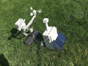
WXLink Support
 The issue is sometimes you don't want to run a wire all the way from the Weather Station to the wind and rain sensor. Using the Mini Pro LP, we built a WeatherRack reader and then we use a transmitter to send
 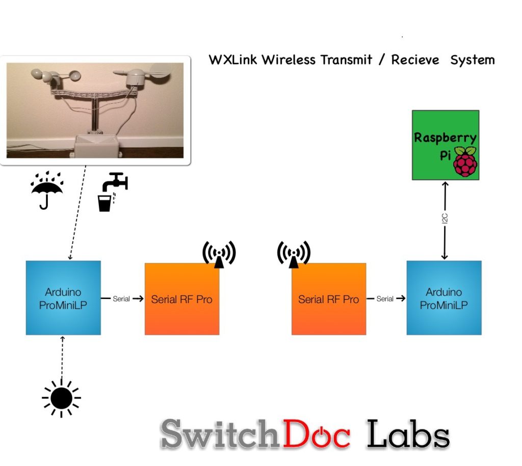 it back to the GroveWeatherPi station inside. And also, sometimes you don't have power easily available and that is why we added a solar power option. The WXLink comes in two version: The WXLink and the Solar WXLink. The Solar WXLink is a solar powered wireless serial link that can transmit up to 600 meters in free air. IT is designed to connect up to any source of data from sensors connected to the Mini Pro LP Arduino compatible low power computer board. It was specifically designed to connect a WeatherRack weather sensor array to a Weather Board based system connected to an Arduino or Raspberry Pi computer. The receiver is read by the host computer through an I2C interface. Much easier and more available than a serial interface. And yes, it has Grove connectors throughout the system. The WXLink comes preloaded with the software to support a WeatherRack and AM2315. See below for the source code. No soldering required.
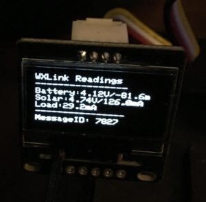
GroveWeatherPi Software Improvements / Changes
The new version (Version 2.8) of the popular GroverWeatherPi Pure Python software for the GroveWeatherPi Raspberry Pi based Solar Powered Weather station kit has been released. You can find it on the SwitchDoc Labs GitHub repository.Scheduler Added - Main Loops Reconstructed
The main architectural change is this version is the conversion of the main loop from a polling based system to a scheduler based task system. Much less processor intensive, more power efficient and a more maintainable program structure. This was done partially in preparation for the Project Curacao2 project. More on that in the next few weeks. The Advanced Python Scheduler (APScheduler) is a light but powerful in-process task scheduler that lets you schedule functions (or any other python callables) to be executed at times of your choosing. We have used the APScheduler software for a number of projects in the past, such as Project Curacao [ref: Raspberry Pi Geek article on Project Curacao], SunRover [ref: Raspberry Pi Geek Article on SunRover software], the upcoming Project Curacao2 project (we revisit wind power and the Caribbean with a 2nd generation Project Curacao) as well as other SwitchDoc Labs projects for customers. It’s a great package. Below is a list of all the current jobs that are scheduled in a running GroveWeatherPi Raspberry Pi Weather Station.-----------------
Scheduled Jobs
-----------------
Jobstore default:
sampleAndDisplay (trigger: interval[0:00:10], next run at: 2017-03-10 16:51:04 PST)
patTheDog (trigger: interval[0:00:10], next run at: 2017-03-10 16:51:04 PST)
blinkSunAirLED2X (trigger: interval[0:00:10], next run at: 2017-03-10 16:51:04 PST)
tick (trigger: interval[0:01:00], next run at: 2017-03-10 16:51:54 PST)
sampleWeather (trigger: interval[0:05:00], next run at: 2017-03-10 16:55:54 PST)
sampleSunAirPlus (trigger: interval[0:05:00], next run at: 2017-03-10 16:55:54 PST)
writeWeatherRecord (trigger: interval[0:05:00], next run at: 2017-03-10 16:55:54 PST)
writePowerRecord (trigger: interval[0:05:00], next run at: 2017-03-10 16:55:54 PST)
updateRain (trigger: interval[0:05:00], next run at: 2017-03-10 16:55:54 PST)
checkForShutdown (trigger: interval[0:05:00], next run at: 2017-03-10 16:55:54 PST)
sampleWeather (trigger: interval[0:15:00], next run at: 2017-03-10 17:05:54 PST)
sampleSunAirPlus (trigger: interval[0:15:00], next run at: 2017-03-10 17:05:54 PST)
doAllGraphs (trigger: interval[0:15:00], next run at: 2017-03-10 17:05:54 PST)
WLAN_check (trigger: interval[0:30:00], next run at: 2017-03-10 17:20:54 PST)
rebootPi (trigger: cron[day='2-30/2', hour='0', minute='4'], next run at: 2017-03-12 00:04:00 PST)
-----------------
HTU21DF and HDC1080 Support
The GroveWeatherPi software now detects and supports both the HTU21DF and the HDC1080 Temperature and Humidity Sensors. They both occupy I2C Address 0x40 but the GroveWeatherPi software can recognize which one is connected. Connecting both of them (on the same I2C bus segment) will result in neither working, but won't damage the devices. The HDC1080 driver software is also pure Python rather than a C based program called by a Python system call. The big two advantages of the HDC1080 over the HTU21DF is it is one half the price and uses a Grove connector to avoid soldering and mistakes. Here is the detection code:###############
# HDC1080 Detection
try:
deviceID = hdc1080.readDeviceID()
#print "deviceID = 0x%X" % deviceID
config.HDC1080_Present = True
except:
config.HDC1080_Present = False
###############
# HTU21DF Detection
if (config.HDC1080_Present == True):
config.HTU21DF_Present = False
else:
try:
HTU21DFOut = subprocess.check_output(["htu21dflib/htu21dflib","-l"])
config.HTU21DF_Present = True
except:
config.HTU21DF_Present = False
###############
Note that detection of the HDC1080 precludes the detection of an HTU21DF. This makes sense as they can't both be there at the same time. Solar Version Bootup Email Message
When you are using a SunAirPlus solar power system with the GroveWeatherPi, on boot up the system now sends an email with the current state of the entire solar battery system. We found ourselves looking for that information all the time on boot up during testing, so it is now included.GroveWeatherPi Version 2.8 Startup BV=4.00V/BC=2.00mA/SV=1.87V/SC=-0.00mA
WeatherUnderGround Support
We recently (Version 2.2) released a version of the GroveWeatherPi software that allows you to connect up your GroveWeatherPi Raspberry Pi Weather Station to the WeatherUnderground. This new version also calculates and reports dew point.Coming Next
The next major release of the GroveWeatherPi software will be building upon the Project Curacao2 software release. It will contain the following:- - Support for the LoRa WXLink system - ranges of greater than 2km. Really! Up to 10km with a good antenna. LoRa is working in the lab and will be part of the Project Curacao2 system because there will be two sets of WeatherRack sensors in the new Project Curacao2. One on a tower about 100m away from the base unit and one on a tower about 2km away up on a ridge. It should be a great project.
- - Support for a PiCamera - Mainly for stills, with an optional video component. Video just kills the battery, but it can be done for a short time.
- - Support for the upcoming GroveControl device that allows the Raspberry Pi to shut off the power to specific Grove devices for power savings. For example, the OLED display. Since Project Curacao2 is 3500 miles away from SwitchDoc Labs, not very many people will be able to read the display very often.
Step 12: Starting the GroveWeatherPi Software

]
Starting the Whole System!
You can now start the GroveWeatherPi software by running the following commands.
From your login directory:cd SDL_Pi_GroveWeatherPi sudo python GroveWeatherPi.pyYou will get a display that looks something like this:
GroveWeatherPi Solar Powered Weather Station Version 2.0 - SwitchDoc Labs


Program Started at:2016-08-12 22:41:31

----------------------
I2C Mux - TCA9545:   		Present
DS3231:   		Present
BMP280:   		Present
FRAM:   		Not Present
HTU21DF:   		Present
AM2315:   		Present
ADS1015:   		Not Present
ADS1115:   		Present
AS3935:   		Present
OLED:   		Present
SunAirPlus:   		Present
----------------------
as3935 Interrupt
processing Interrupt from as3935
Last Interrupt = 0x4:  Disturber detected - masking
----------------------------------------
----------------------------------------
----------------------------------------
----------------------------------------
----------------------------------------
----------------------------------------
----------------------------------------
----------------------------------------
----------------------------------------
----------------------------------------
-----------------
 WeatherRack Weather Sensors Sampling
-----------------
Rain Total=	0.00 in
Wind Speed=	0.00 MPH
MPH wind_gust=	0.00 MPH
Wind Direction=			 270.00 Degrees
Wind Direction Voltage=		 4.476 V
-----------------
-----------------
 DS3231 Real Time Clock
-----------------
Raspberry Pi=	2016-08-12 22:41:41
DS3231=		2016-08-12 22:41:41
DS3231 Temperature= 	25.25 C
-----------------
-----------------
-----------------
 BMP280 Barometer
-----------------
Temperature = 	25.60 C
Pressure = 	94.66 KPa
Altitude = 	570.64 m
Sealevel Pressure = 	94.66 KPa
-----------------
-----------------
 HTU21DF Temp/Hum
-----------------
Temperature = 	24.70 C
Humidity = 	43.40 %
-----------------
-----------------
 AS3935 Lightning Detector
-----------------
Last result from AS3935:
Disturber: Disturber detected - masking
Lightning Count =  0
-----------------
-----------------
 AM2315 Temperature/Humidity Sensor
-----------------
outsideTemperature: 24.4 C
outsideHumidity: 36.9 %
crc: 1
-----------------
-----------------
SunAirPlus Currents / Voltage
-----------------
LIPO_Battery Bus Voltage: 3.78 V
LIPO_Battery Shunt Voltage: -14.56 mV
LIPO_Battery Load Voltage:  3.76 V
LIPO_Battery Current 1:  -145.60 mA
Battery Power 1:  -0.55 W

Solar Cell Bus Voltage 2:  4.75 V
Solar Cell Shunt Voltage 2: -40.64 mV
Solar Cell Load Voltage 2:  4.71 V
Solar Cell Current 2:  406.40 mA
Solar Cell Power 2:  1.91 W

Output Bus Voltage 3:  4.94 V
Output Shunt Voltage 3: 18.88 mV
Output Load Voltage 3:  4.94 V
Output Current 3:  188.80 mA
Output Power 3:  0.93 W
Add a Bootup Start for GroveWeatherPi
The final system step you need to do is to add a line to startup GroveWeatherPi when your Raspberry Pi reboots. If you don’t do this, then you have to start it manually which doesn’t work with the WatchDog or if the station runs out of energy.
On your Pi, edit the file /etc/rc.local using the editor of your choice. You must edit with root, for example:sudo nano /etc/rc.local
Add commands below the comment, but leave the line exit 0 at the end, then save the file and exit.
Add the following command (all on one line) to the file before the exit 0 line.cd /home/pi/SDL_Pi_GroveWeatherPi; sudo python /home/pi/SDL_Pi_GroveWeatherPi/GroveWeatherPi.py >> /home/pi/GroveWeatherPi.log &Now reboot your machine by typing:
sudo rebootLogin in again and you can look at the output of GroveWeatherPi by running the following command in /home/pi
tail -f GroveWeatherPi.log
Running on AC Power
Want to run inside on AC power? Plug a 5V Mini USB power supply into SunAirPlus.
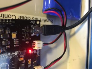 Plugging in a Power Supply to SunAirPlus
Remove OLED Display
Turn off the power now and remove the OLED display from the box, as we won’t be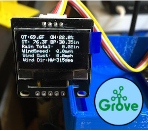 looking at it once we shut the box. Alternatively, you can leave the display in (it takes about 15mA) and put a small plexiglass window on the side of the box to read it.
Step 13: The Final Assembly Step and the Control Panel


The Final Step
Your final step is to connect the wire shown in the table below. This wire allows the WatchDog timer to turn off the power to the Weather Station if the WatchDog expires. The reason you haven’t connected this wire yet is that you haven’t been running GroveWeatherPi.py which “Pats the Dog” and keeps this form happening. If you are are going to be doing a lot of development or changes, it is a good thing to remove this wire or run another program that “Pats the Dog” while you are developing.| WatchDog Board JP5/ArduinoReset | USB PowerControl TP3/COUT - Soldered To Pad (DO NOT CONNECT THIS WIRE UNITL YOU ARE DONE TESTING AND MODIFYING THE SOFTWARE!) | Cut one end of 12 inch Female to Female Header Jumper Wire and solder it to TP3/COUT pad as shown below |
Building A Control Panel Using RasPiConnect
We use RasPiConnect ( www.milocreek.com ).to build our control panels for our projects. It allows us to put graphs, controls, buttons, sliders, etc. up on our iPad/iPhone screens without having to write apps. RasPiConnect works on Raspberry Pi's and on Arduinos. We have used this software on 5 different projects, with GroveWeatherPi being the latest.
How to build a control panel for GroveWeatherPi is beyond the scope of this Chapter, but here is the tutorial ( http://www.switchdoc.com/2014/07/build-control-panels-tutorial-raspiconnect/ ) we wrote for doing what we are doing for GroveWeatherPi. We are using the same command passing mechanism in GroveWeatherPi that we used in MouseAir. RasPiConnect comes with an excellent, comprehensive manual here ( www.milocreek.com ) .
All the RasPiConnect code that we used in this project is on github under github.com/switchdoclabs. Note that only the directory local is in the repository as that is the only places changes to the code are made as explained in the RasPiConnect manual.
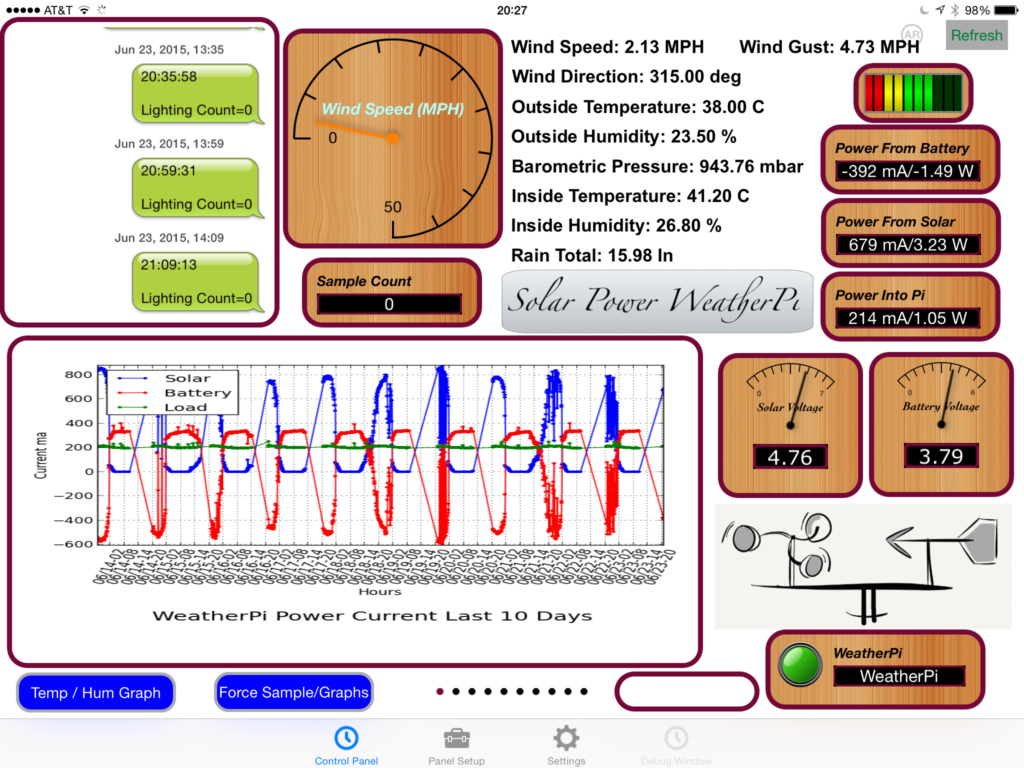 RasPiConnect Control Panel Showing Solar Current Graphs
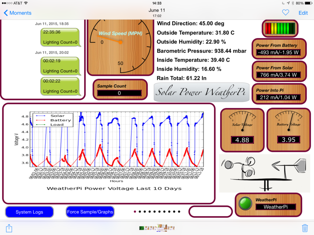 RasPiConnect Control Panel Showing Solar Voltage Graphs
Step 14: Add Your GroveWeatherPi to the WeatherUnderground


We have just released a new version of the GroveWeatherPi software that allows you to connect up your GroveWeatherPi Raspberry Pi Weather Station to the WeatherUnderground.
Version 2.2 - SDL_Pi_GroveWeatherPi at github.com
Changes:
- - Support for WXLink Wireless WeatherRack Hardware
- - Improved configuration options for MySQL and WLAN Detection
- - WeatherUnderground reporting now supported
- - Adding Your GroveWeatherPi Station to the WeatherUnderground
Instructions to Connect
- Go to weatherunderground.com and register your PWS (Personal Weather Station) on the site. You will need to sign up to be a user.
2. When you have registered your station, put your station name and key in the config.py file and enable the WeatherUnderground_Present by setting it to True.
# WeatherUnderground Station

WeatherUnderground_Present = False
WeatherUnderground_StationID = "KWXXXXX"
WeatherUnderground_StationKey = "YYYYYYY"
Then you can start the software normally. The software is set to report to the WeatherUnderground every 5 minutes, so wait a bit before checking.
Status
Our development system is up and down as well as sensors being disconnected and connected, but if you want to see it, here is the link:
https://www.wunderground.com/personal-weather-station/dashboard?ID=KWALIBER13
We will be adding another full station that will be running all the time in the near future. The box is built, but has to be shipped to England for photographing for a new book that features the GroveWeatherPi Solar Powered version.
Step 15: Results and Conclusions


Results!
The GroveWeatherPi has been outside for about 2 weeks now. Working perfectly. You can see the box being charged up and then going to battery power as the sun moves behind the house. We have had hot days and cold nights as we are just starting to move out of Summer into Fall. It is not quite generating enough electricity to run 24 hours at the moment (because it is in the shade until 9am and after about 3pm - not quite 8 hours of sun). This will be fixed when we move it up to the top of the house where it will have sun about 12 hours a day on average (when the sun is not behind clouds!).
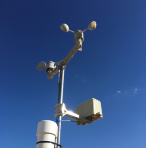 WeatherRack on PVC Pole
The cheap RT5370 Wireless Adapter WiFi dongle we are using is shutting itself down occasionally. The Raspberry Pi keeps running, collecting data, etc., but we are locked out of the system. When we look at the WiFi adaptor when it has shut itself down, it is no longer blinking blue, but the Raspberry Pi and all the external hardware is still running. Looking at the web shows some people having had similar problems with this dongle. We have now replaced it with a WiPi USB Dongle which works well. Interestingly enough, the WiPi USB dongle reports it is using the RT5370 also, but the WiPi works.
Full GroveWeatherPi Ready for Installation
Improvements
We aren't building graphs for the Wind Speed, Direction and Rain yet. Just reporting the current values on the RasPiConnect control panel. All the data is being saved into MySQL, however.
The temperature and lightning displays need to be fixed and improved. The cool thing is that all of this can be done remotely! Remember that you still have to “Pat the Dog” if you shutdown the GroveWeatherPi software.
What Else Can You Do With This?
Here are some additional ideas for projects based on GroveWeatherPi:
- Replacing the WiFi with a GSM data connection (or just send text messages)
- Make it tweet the weather!
- Make a custom Facebook posting with your weather
- Adding a GPS receiver and store that data. You now have a mobile weather station! When it gets back to WiFi all the stored data will be available.
- Adding additional air quality sensors, UV sensors, Dust sensors. You have a lot of I2C addressing space that you can fill
Conclusion
The GroveWeatherPi is a great project for learning how to prototype and build projects with your Raspberry Pi. This is a full fledged weather station with many sensors and functions. Stay tuned to switchdoc.com as we will be adding tutorials on how to install CWOP, Twitter, Weeex, WeatherUnderground, MQTT and others!

Participated in the
Solar Contest 2016


