

Introduction: Hacking an Arduino ISP Shield for AtTiny45 / AtTiny85
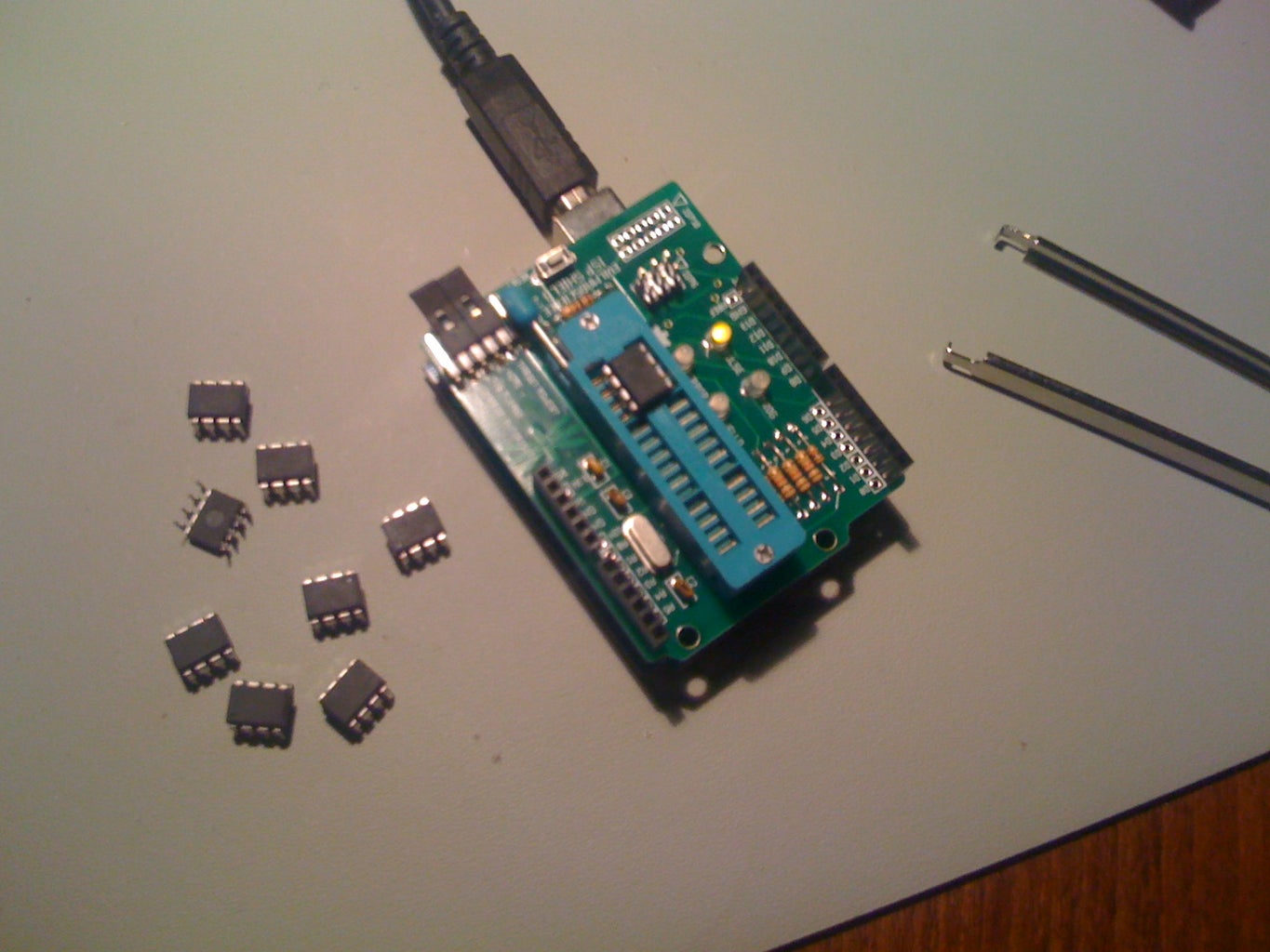
This is how to hack an Evil Mad Scientists Lab Arduino ISP Shield so that you can use the Arduino environment to program some nifty little microcontrollers.
The Arduino is a great little development environment for creating electronic projects http://www.arduino.cc/ but there are times when you just want the minimum possible pieces, and don't want the expense, or size, of a full Arduino plus breadboard/prototyping shield.
That's when you want to use a dinky microcontroller.
Fortunately AtMel (who make the AtMega inside the Arduino) also make a bunch of little ones called AtTiny. These range from 6 pin to 28 pin chips, and use almost the same instruction set as the big guys - they are part of the same AVR family.
My chip of choice for these kinds of projects is the ATtiny85
It has 8K of program memory, comes in a PDIP 8 pin package and has 5 (or 6) I/O pins. It also has 512 bytes of static RAM, and 512 bytes of EEPROM. It can run on two AA batteries (3 Volts, some version will go as low a 1.8V), and doesn't use much power.
For the technically inclined see http://www.atmel.com/dyn/resources/prod_documents/2586S.pdf for a summary of its capabilities.
Step 1: Things You Will Need

Arduinohttp://arduino.cc/en/Main/Hardware
- for this instructable an older Arduino is better than the latest. The UNO has a problem, soon to be resolved, which prevents it from working as an ISP. I use a Diecimila with an older atMega168 - this is a good use of an older device.
- if you don't already have one, I can recommend Adafruit http://www.adafruit.com/ as a supplier
Arduino ISP Shieldhttp://evilmadscience.com/productsmenu/tinykitlist/253
- this image is from EMSL website
- build the ISP kit, and make sure it works.
- you most likely will want the jumper connection set to
OVERRIDE AUTORESET - YES PLEASE
- also load the Arduino ISP example sketch Files -> Examples -> ArduinoISP and upload it into your Arduino.
Software follow the instructions here: http://hlt.media.mit.edu/wiki/pmwiki.php?n=Main.ArduinoATtiny4585
- this is a really nice page with good information about how you can wire up your own breadboard to achieve the same thing.
- in particular you will need to install the AtTiny45_85 support files http://hlt.media.mit.edu/wiki/uploads/Main/attiny45_85.zip
Microcontrollers
- AtTiny45 or AtTiny85 chips to program - they are available from Mouser, DigiKey and many other places.
Miscellaneous
- connecting wire - I used bits of wire wrap because it is small and neat; but any insulated wire, you can solder, will do!
Step 2: Wiring

You will need to solder five small wires on the bottom of the Arduino ISP Shield.
Flip the board over and locate pin 1 of the ZIF socket. This is the one nearest the lever switch, and will be at the top-right when the board is flipped over (component side down). it's handy to mark this pin.
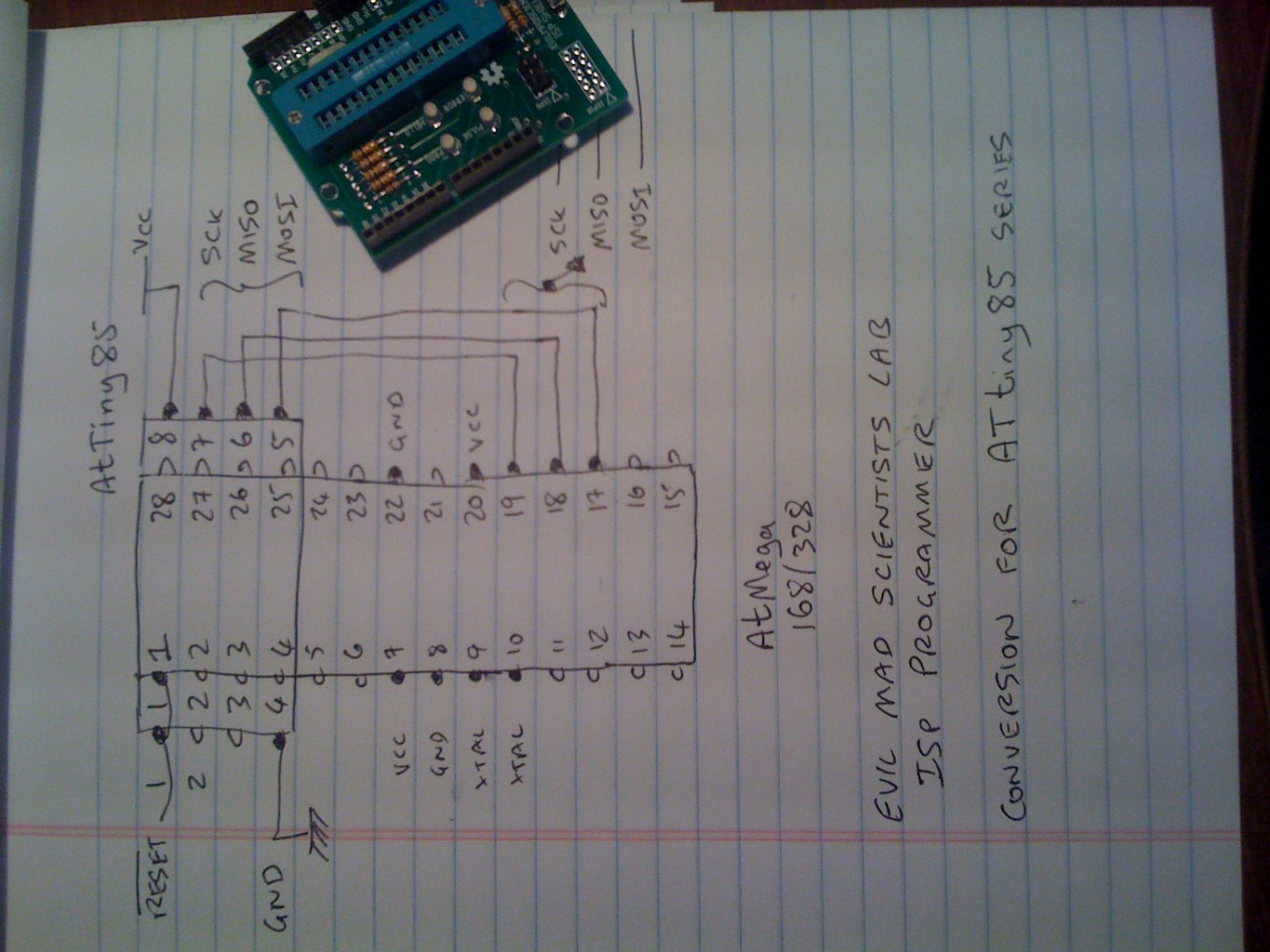
The diagram show the wring from the top, but the picture of the board shows what it will look like when you are done.
Connect Pin 4 to Pin 8 - this is the ground connection.
Connect Pin 28 to Pin 20 - this is the Vcc (+5 Volts)
Connect Pin 27 to Pin 19 - SCK - Serial Clock
Connect Pin 26 to Pin 18 - MISO - Serial Out
Connect Pin 25 to Pin 17 - MOSI - Serial In
Pin 1 - RESET is already connected on the board so we don't need to touch that.
Use a multimeter to check the connections - it is easy to short out adjacent pins as they are only 1/10" apart.
Step 3: Using

After installing the AtTiny45_85 support files (see step 2), open up the Arduino IDE, and look under the Tools -> Boards menu.
You should see new entries for AtTiny45 and AtTiny85. We are using AtTiny85 (w/ Arduino as ISP)
Insert an AtTiny85 in the ZIF socket. lined up at the top of the socket, so pin one is nearest the lever. Pin 1 is the pin next to the little circular dot.
Write a small test sketch - or use the BLINK example Files -> Examples -> Basic -> Blink - remember to change the digital pin from 13 to 0 - the AtTiny chips don't have a digital 13 !
Compile and Upload the Sketch!
Step 4: Conclusion
Have fun with this.
If it doesn't work at first attempt: check the source links:
http://wiki.evilmadscience.com/Using_The_ISP_Shield_2
http://hlt.media.mit.edu/wiki/pmwiki.php?n=Main.ArduinoATtiny4585
http://arduino.cc/en/Tutorial/ArduinoISP
and ask questions...!
Special thanks to Dr Who at Evil Mad Scientists Labs for answering all the crazy questions from me and others on the EMSL Forums!


