

Introduction: Hall Effect Sensors 1: Position Control


In this Instructable we will be learning how to use interrupts on the Arduino to track the hall effect sensors in a motor to track position. This is Part 1 of a 3 part series, next week we will learn about synchronizing the speed of two motors so they move together and in the third part we will cover more advanced PID control.
Part 2: https://www.instructables.com/id/Hall-Effect-Sensor...
Part 3: https://www.instructables.com/id/Hall-Effect-Sensors-3-PID-Control/
For this Instructable, we will need:
- Actuator with Hall Effect sensor
- MegaMoto motor control shield
Let's get started!
Step 1: Hall Effect Sensors

Hall effect sensors measure the strength of a nearby magnetic field. By attaching a magnet to the shaft of the motor, the sensors can detect when the shaft is parallel to them. Using a small circuit board, this information can be output as a square wave, which can be counted as a string of pulses. By counting these pulses you can keep track of how many times the motor has spun and how the motor moves.
Some hall effect boards have multiple hall effect sensors on them. It is common for them to have 2 sensors (A and B) at 90 degrees. By counting these pulses and seeing which comes first (A before B, or B before A) you can tell the direction that the motor is spinning. Or you can just monitor both sensors and get more counts for more precise control.
Step 2: Hardware Setup


The hall effect sensors have 4 wires: 5V, GND, and 2 Signal wires. Each signal wire gives out pulses as the motor spins. There are also the two actuator wires to connect to the MegaMoto. We are only using one of the hall effect signals.
Connect as follows:
- Red wire to 5V
- Black wire to GND
- Yellow/Orange wire to Arduino pin 2 or 3 (Important)
- Actuator red wire to MOTA of the MegaMoto
- Actuator black wire to MOTB of the MegaMoto
Make sure to check the beginning of the code in the next step. Ensure that the jumpers on the MegaMoto and the hall effect sensors are all set to the correct pins. Ensure that "hall0" and "hall1" correspond to the correct MegaMotos (PWMA0 and PWMA1 respectively).
Once the motors are wired correctly to the boards, wire as follows:
- Connect 12V to BAT+
- Connect GND to BAT-
- Connect 12V to Vin on the Due
- Wire two buttons between pins 7 and 8, connecting them to GND
The Arduino pin selection of 2 or 3 is crucial. The Arduino Uno has 2 interrupt pins that can be used. If you have an Arduino Mega you have 6 interrupts that can be used (2, 3, 18, 19, 20, 21) and with a Due you can use every pin as an interrupt. In the next step we will look at the programming that will enable these pins as interrupts.
Step 3: Interrupts

Using Ardunio pins 2 and 3 on the Uno is very important. We are going to be using the interrupt function of the Arduino.
Interrupts are a type of subroutine, usually very small. They should only be a few lines of code and they need to execute as fast as possible. Usually when code runs it goes through line by line, running the instructions sequentially. When you use interrupts, interrupt the code and execute as soon as the trigger condition is true. We are going to trigger an interrupt whenever the encoder gives pulses and use that to keep count. This allows us not to lose track of counts.
There are 4 types of triggers for the interrupt: Rising, Falling, High, and Low. By changing the trigger you can adjust when the interrupt happens. Rising is whenever the pin sees a transition from low to high, falling is when it sees high to low, low is when the pin is low and high is when the pin is high.
Below is a small snippet of code, showing the basic interrupt we will use. There are comments to further explain.
volatile int count = 0;//if the interrupt will change this value, it must be volatile

void setup() {
 pinMode(2, INPUT); set as input
 digitalWrite(2, HIGH);//enable internal pullup resistor
 attachInterrupt(digitalPinToInterrupt(2), interruptName, RISING);//Interrupt initialization
 Serial.begin(9600);
}//end setup

void loop() {
  Serial.println(count);//see the counts advance
  delay(100);//Delays usually can't be interfered with, here we will see the interrupt work
}//end loop

void interruptName()
{
  count = count+1;
}//end Interrupt Service Routine (ISR)
Usually it is poor form to use a Serial.print() in an interrupt. Serial.prints() are a very computational intense task, they take a long time to happen. When you are in an interrupt you cannot be interrupted by a second one. If you are counting pulses and the interrupt is too long you will lose counts.
For more details, see this page: www.arduino.cc/en/Reference/AttachInterrupt
Step 4: Position Control
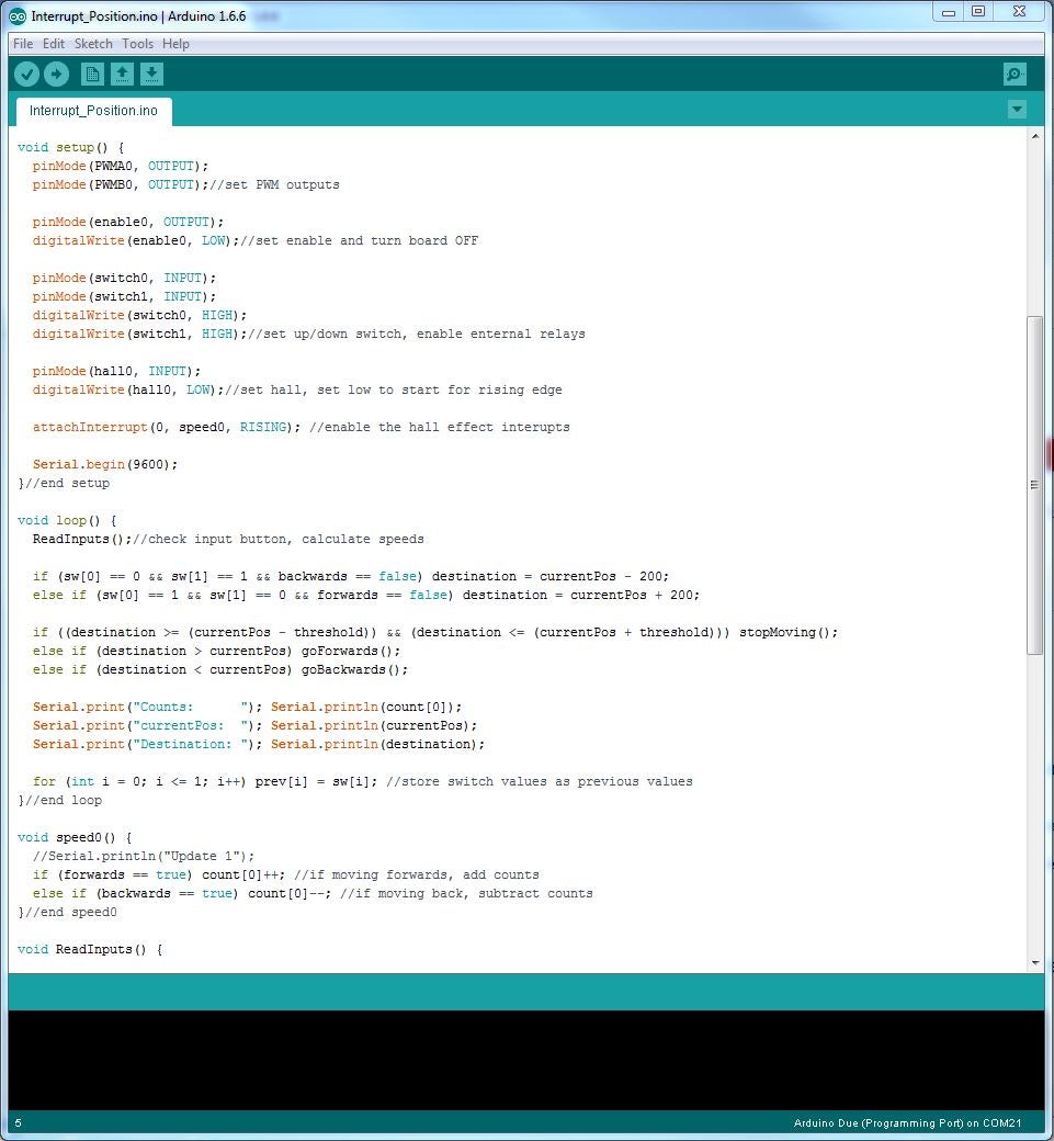
Now that we've seen a basic interrupt we can expand it to control the motor. We are going to use a single variable and then depending if the actuator is going forwards or backwards we will add or subtract from the value.
The subroutine speed0() will be linked to the interrupt. By knowing the current position and calculating the destination position we know which direction to send the motor. Keep in mind that the counts may not be perfect. If you run the motor for a long time back and forth you may lose a count here and there and slowly lose track of where you are. We will use a homing routine (see next step) to help keep everything in check.
The attached code will move the actuator forwards or backwards by a set amount when you press the buttons on pin 7 or 8 (active LOW). You can test it by using a wire attached to GND.
See the attached code below for more details.
#define PWMA0 6
#define PWMB0 5
#define enable0 13   //pins for first MegaMoto

#define switch0 7   //Up button
#define switch1 8   //Down button

#define hall0 2 //interrupt pins for hall effect sensors

int enable = 0; //enable pin for megaMoto

int count[] = {0};//Actuator

int sw[] = {1, 1}; //switch up, switch down
int prev[] = {0, 0};//previous switch state

int currentPos = 0;//current position
int threshold = 1;
int destination = 0;

bool forwards = false;
bool backwards = false;// motor states

bool firstRun = true;//first run of the motor once the button is pushed

void setup() {
  pinMode(PWMA0, OUTPUT);
  pinMode(PWMB0, OUTPUT);//set PWM outputs
  pinMode(enable0, OUTPUT);
  digitalWrite(enable0, LOW);//set enable and turn board OFF

  pinMode(switch0, INPUT);
  pinMode(switch1, INPUT);
  digitalWrite(switch0, HIGH);
  digitalWrite(switch1, HIGH);//set up/down switch, enable enternal relays

  pinMode(hall0, INPUT);
  digitalWrite(hall0, LOW);//set hall, set low to start for rising edge
  attachInterrupt(0, speed0, RISING); //enable the hall effect interupts

  Serial.begin(9600);
}//end setup

void loop() {
  ReadInputs();//check input button, calculate speeds

  if (sw[0] == 0 && sw[1] == 1 && backwards == false) destination = currentPos - 200;//dont change destination while moving
  else if (sw[0] == 1 && sw[1] == 0 && forwards == false) destination = currentPos + 200;//dont change destination while moving

  if ((destination >= (currentPos - threshold)) && (destination <= (currentPos + threshold))) stopMoving();//stop if you're close enough
  else if (destination > currentPos) goForwards();//move if you need to
  else if (destination < currentPos) goBackwards();//move if you need to

  for (int i = 0; i <= 1; i++) prev[i] = sw[i]; //store switch values as previous values
}//end loop

void speed0() {
  if (forwards == true) count[0]++; //if moving forwards, add counts
  else if (backwards == true) count[0]--; //if moving back, subtract counts
}//end speed0

void ReadInputs() {
  sw[0] = digitalRead(switch0), sw[1] = digitalRead(switch1);//check switches
  currentPos = count[0];//set where you are
}//end read inputs

void goForwards()
{
  forwards = true;
  backwards = false;//set travel direction
  digitalWrite(enable0, HIGH);//enable board
  analogWrite(PWMA0, 255);
  analogWrite(PWMB0, 0);//apply speeds
}//end goForwards

void goBackwards()
{
  forwards = false;
  backwards = true;//set travel direction
  digitalWrite(enable0, HIGH);//enable board
  analogWrite(PWMA0, 0);
  analogWrite(PWMB0, 255);//apply speeds
}//end goBackwards

void stopMoving()
{
  forwards = false;
  backwards = false;//set travel direction
  analogWrite(PWMA0, 0);
  analogWrite(PWMB0, 0);//set speeds to 0
  delay(10);
  digitalWrite(enable0, LOW);//disable board
}//end stopMoving
Attachments

Step 5: Homing

Please ensure the MegaMoto current sense pin is on A5, and across A2, and A3.
Even when we try our best to count every pulse there may be occasions that we may miss a few and slowly lose precision over time. To minimize this we can use a homing routine! The idea is to send the actuator to a predetermined position (fully extended or fully retracted) and set the counts to a known value. Usually it is easiest to fully retract the actuator and set the counts to 0. In the code below it will reset to a maximum counts value when fully extended and reset to 0 when fully retracted.
To do so you need a way to tell when the motor is at it's limits. Here we will use the current sensing of the MegaMoto to watch when the current drops to 0. When it does we can see that the actuator has hit the limit switch and stopped moving. We have a small counter running because sometimes the current can report a false 0. By making sure that the current is 0 for a length of time we know that the motor really is at a limit and isn't getting false readings.
See attached code and comments for more information:
#define amp0 A5

#define PWMA0 6
#define PWMB0 5
#define enable0 13   //pins for first MegaMoto

#define switch0 7   //Up button to add counts
#define switch1 8   //Down button to subtract counts

#define hall0 2 //interrupt pins for hall effect sensors

int enable = 0; //enable pin for megaMoto
int lowampLimit = 0;//Low limit to detect when actuator stops
int amps = 0; //current readings
int timedelay[] = {750, 50}; //first, regular delay for feedback

int hitLimits = 0;
int hitLimitsmax = 10;//value for knowing when retracted

int count[] = {0};//Actuator
int maxCounts = 1150;//number of counts when fully extended

int sw[] = {1, 1}; //switch up, switch down
int prev[] = {0, 0};//previous switch state

int currentPos = 0;//current position
int threshold = 1;
int destination = 0;

bool forwards = false;
bool backwards = false;// motor states

bool extended = false;
bool retracted = false;//actuator positions

bool firstRun = true;//first run of the motor once the button is pushed

void setup() {
  pinMode(amp0, INPUT);
  digitalWrite(amp0, LOW);//set Current sensors
  pinMode(PWMA0, OUTPUT);
  pinMode(PWMB0, OUTPUT);//set PWM outputs
  pinMode(enable0, OUTPUT);
  digitalWrite(enable0, LOW);//set enable and turn board OFF

  pinMode(switch0, INPUT);
  pinMode(switch1, INPUT);
  digitalWrite(switch0, HIGH);
  digitalWrite(switch1, HIGH);//set up/down switch, enable enternal relays

  pinMode(hall0, INPUT);
  digitalWrite(hall0, LOW);//set hall, set low to start for rising edge
  attachInterrupt(0, speed0, RISING); //enable the hall effect interupts

  retracted = true;//start retracted
  extended = false;

  Serial.begin(9600);
}//end setup

void loop() {
  ReadInputs();//check input button, calculate speeds

  if (sw[0] == 0 && sw[1] == 1 && backwards == false) destination = currentPos - 115;//dont change destination while moving
  else if (sw[0] == 1 && sw[1] == 0 && forwards == false) destination = currentPos + 115;//dont change destination while moving

  Serial.print("count[0]    "); Serial.println(count[0]);
  Serial.print("currentPos  "); Serial.println(currentPos);
  Serial.print("destination "); Serial.println(destination);

  if ((destination >= (currentPos - threshold)) && (destination <= (currentPos + threshold))) stopMoving();//stop if you're close enough
  else if (destination > currentPos) goForwards();//move if you need to
  else if (destination < currentPos) goBackwards();//move if you need to

  for (int i = 0; i <= 1; i++) prev[i] = sw[i]; //store switch values as previous values
}//end loop

void speed0() {
  if (forwards == true) count[0]++; //if moving forwards, add counts
  else if (backwards == true) count[0]--; //if moving back, subtract counts
}//end speed0

void ReadInputs() {
  amps = analogRead(amp0);//read current
  sw[0] = digitalRead(switch0), sw[1] = digitalRead(switch1);//check switches
  currentPos = count[0];//set where you are
}//end read inputs

void goForwards()
{
  forwards = true;
  backwards = false;//set travel direction
  getFeedback();//check current draw
  digitalWrite(enable0, HIGH);//enable board
  analogWrite(PWMA0, 255);
  analogWrite(PWMB0, 0);//apply speeds
}//end goForwards

void goBackwards()
{
  forwards = false;
  backwards = true;//set travel direction
  getFeedback();//check current draw
  digitalWrite(enable0, HIGH);//enable board
  analogWrite(PWMA0, 0);
  analogWrite(PWMB0, 255);//apply speeds
}//end goBackwards

void stopMoving()
{
  forwards = false;
  backwards = false;//set travel direction
  analogWrite(PWMA0, 0);
  analogWrite(PWMB0, 0);//set speeds to 0
  delay(10);
  digitalWrite(enable0, LOW);//disable board
}//end stopMoving

void getFeedback()
{
  amps = analogRead(amp0);
  Serial.print(" Amp readings - "), Serial.println(amps);

  if (amps <= lowampLimit && hitLimits < hitLimitsmax) hitLimits = hitLimits + 1;
  else hitLimits = 0;

  if (hitLimits == hitLimitsmax && backwards == true)
  {
    Serial.println("RETRACTED");
    retracted = true;
    count[0] = 0; //reset counter when homed
    destination = 0;
  }

  if (hitLimits == hitLimitsmax && forwards == true)
  {
    Serial.println("EXTENDED");
    extended = true;
    count[0] = maxCounts; //reset counter when extended
    destination = maxCounts;
  }
 }//end getFeedback
Step 6: Conclusion

In this Instructable we learned how interrupts worked and then used a hall effect sensor to track the position of an actuator. This was part 1 in a three part series, next week we will go over speed control and using multiple actuators together.
If you'd like to take a look at our selection of linear actuators, motions control systems and microcontrollers then please visit us at www.progressiveautomations.com for all your actuator needs! We can even build a custom actuator or control system for you based on your own custom specifications with the help of our highly trained staff of engineers. You can learn more about the custom order process right here!
Follow, Like and Subscribe!
Twitter -www.twitter.com/ProgAutoInc
Facebook -www.facebook.com/ProgressiveAutomations


