

Introduction: Handcrafted Arduino-powered RGB Moodlamp


- Planning the construction (Step1)
- The handmade shade (Step2+3)
- The electronic circuit for driving 3W LEDs with the ATmega8 controller (Step4)
- The Code (Step5)
- How to get it stand-alone (flash the Arduino bootloader with PonyProg and burn the sketch) (Step6) coming soon
Vid: Some Impressions
http://de.youtube.com/watch?v=apZ9NpaUG84
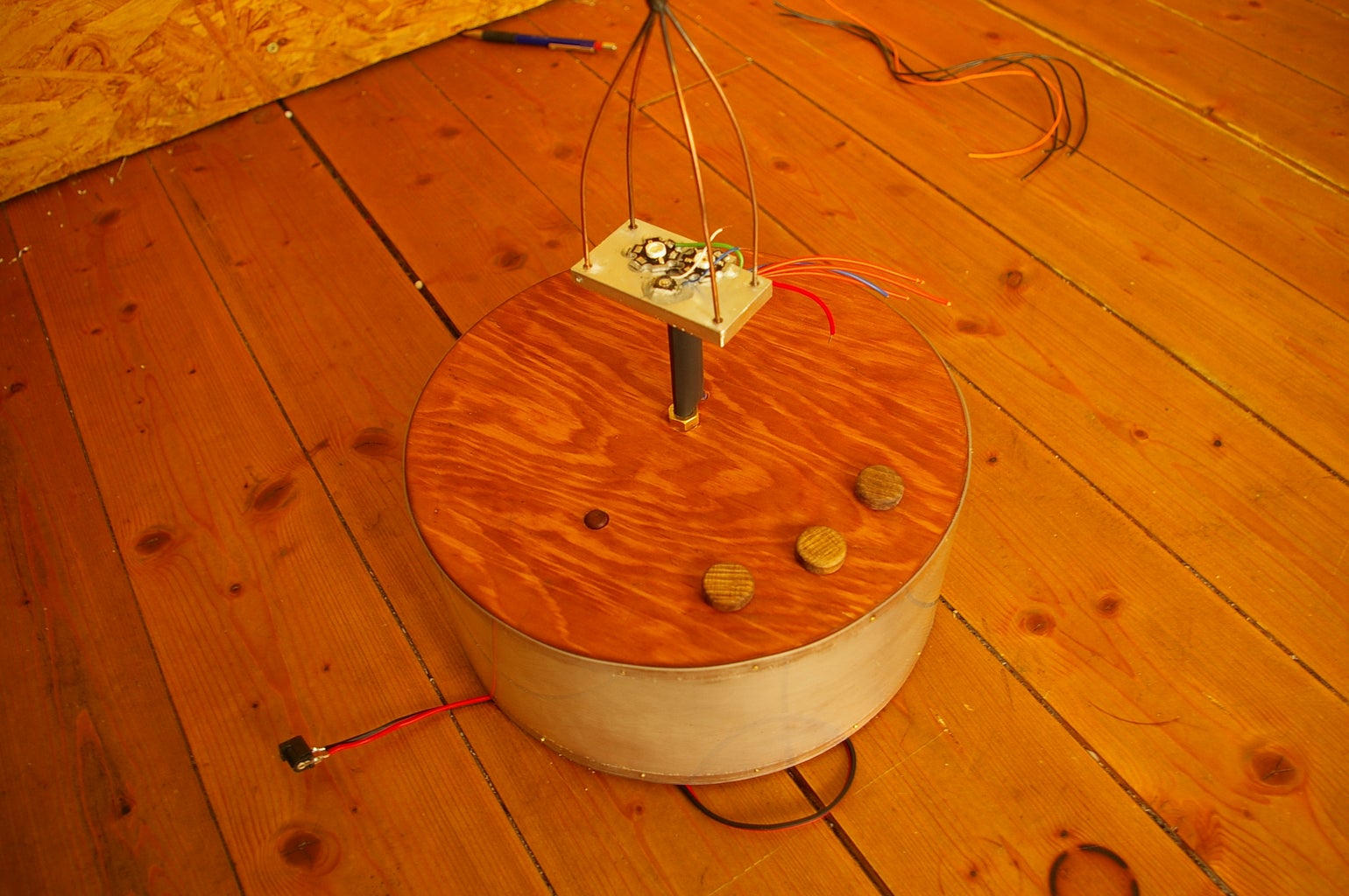
Pic1: The Moodlamp
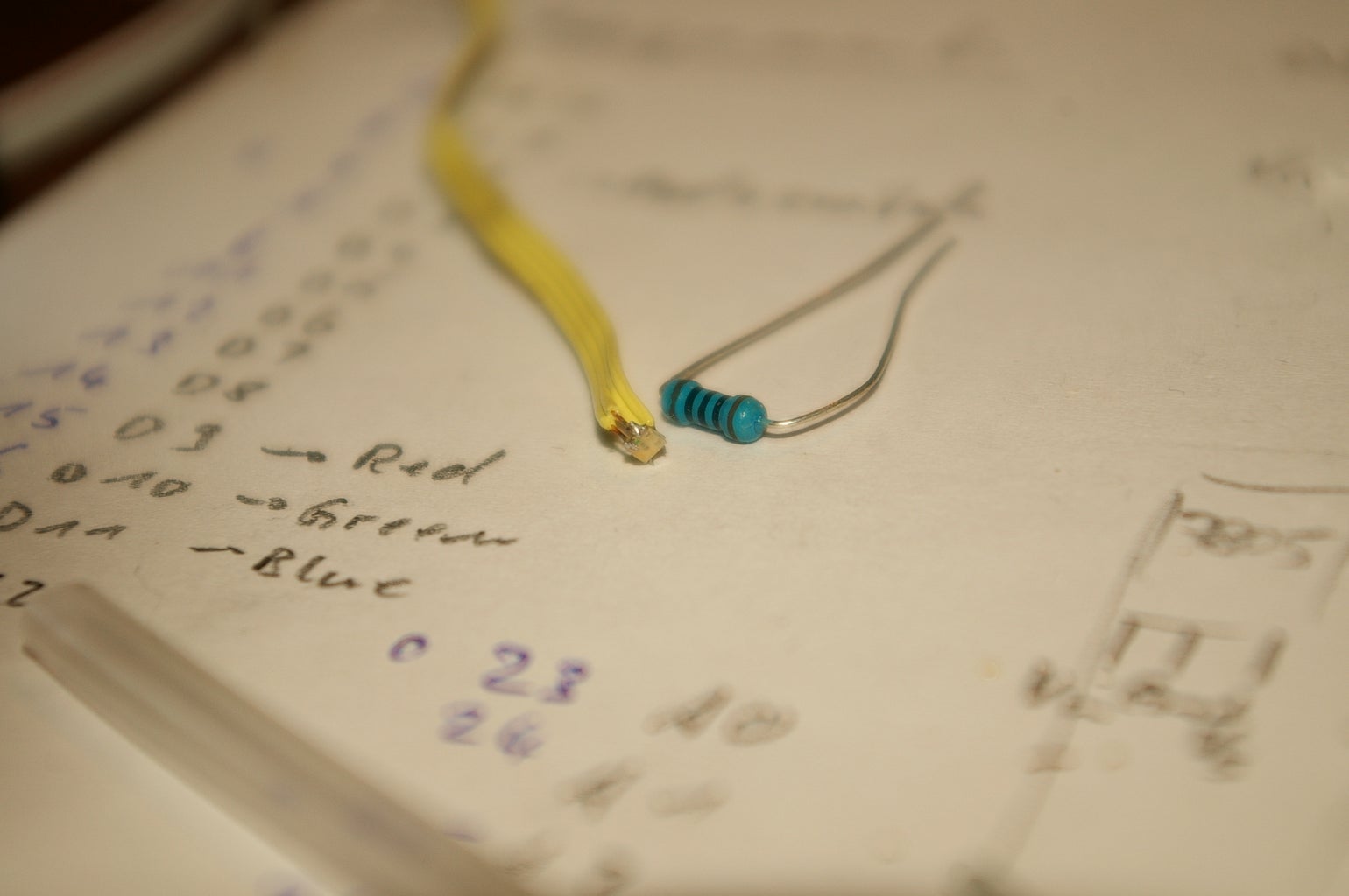
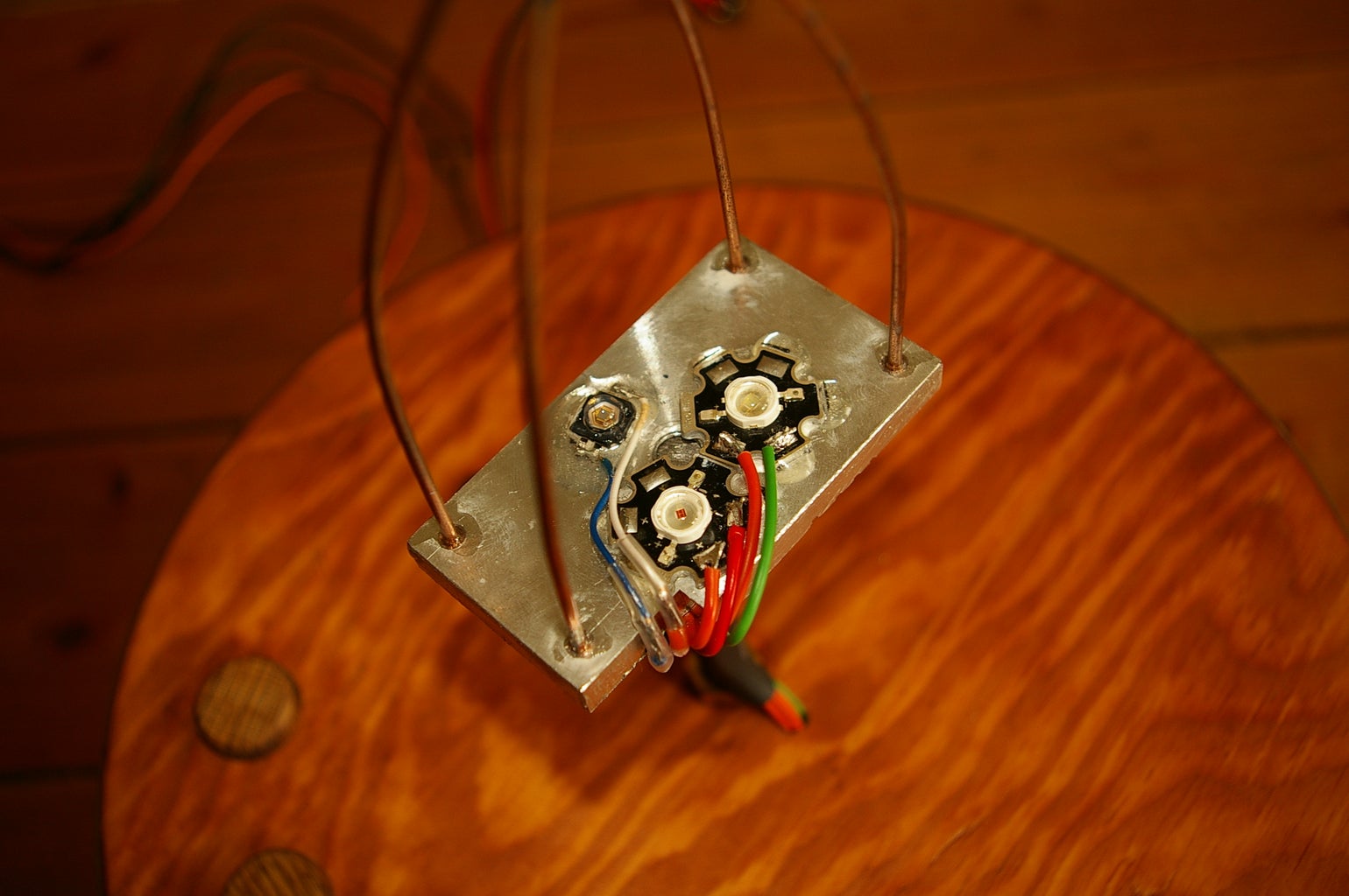
Pic2: A mighty 3W LED
Step 1: Planning the Construction:

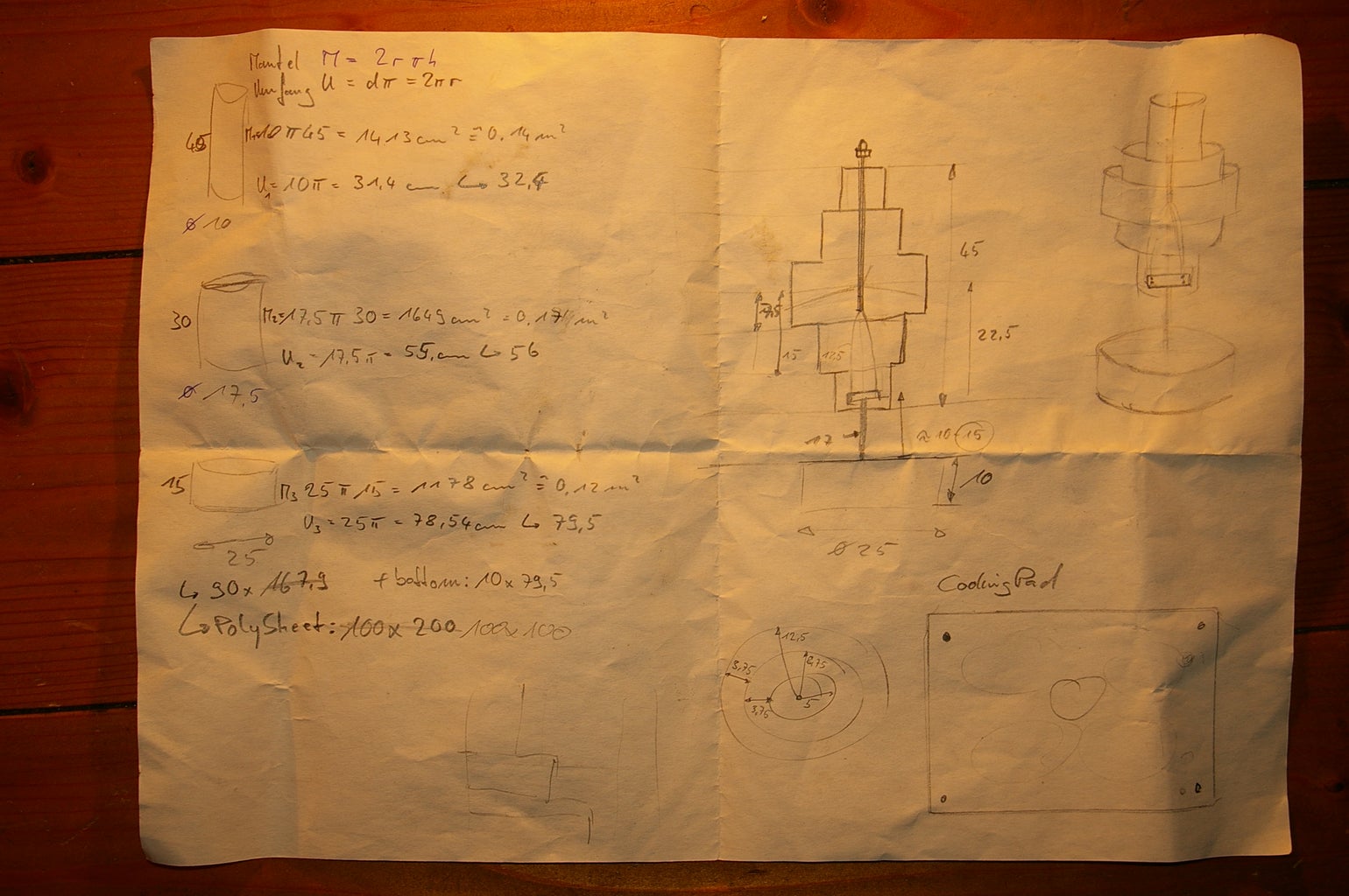
I love to do a concept on just one sheet of paper.
On the first sheet you see some early ideas. "I chose the bottom-right design.
The second page shows some details for the construction.
measurements are experimental like each time, but ok for me ;-)
My hardware thoughts were:
- Can I handle the materials?
- Will the light shine through the shade?
- What proportion should it have?
- How many knobs and pots will I need for a simple interface?
My software thoughts were:
How many different functions should the lamp have?
- Automatic RGB fading with changeable speed
- Manual color adjustment
- White with adjustable brightness
Step 2: The Handmade Shade


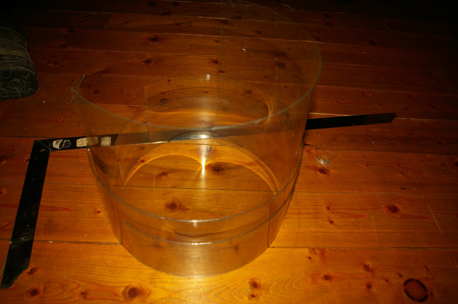


Gathering the materials:
The shade:
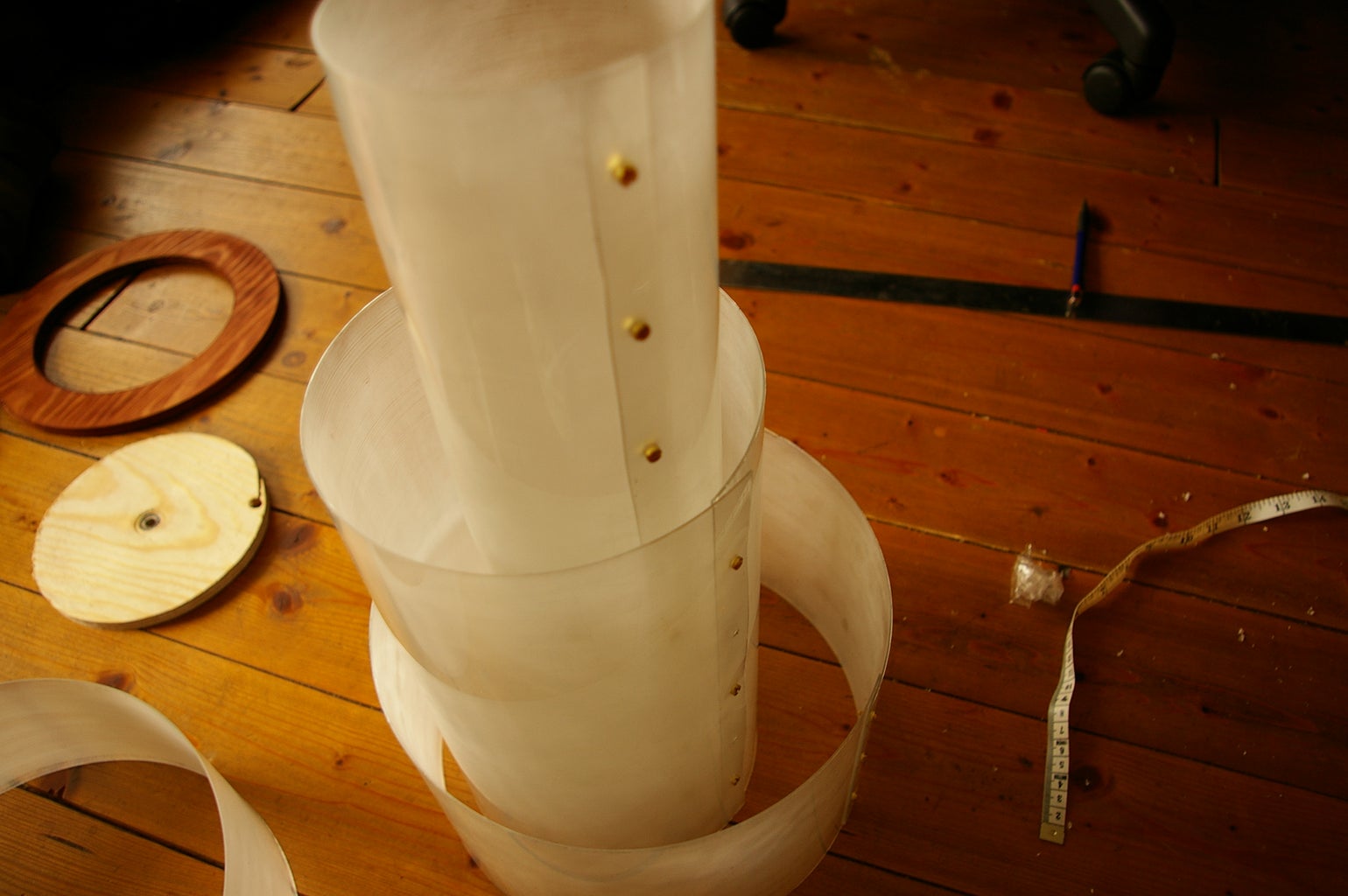
I found a 3 foot x 3 foot sheet of 30 mill plastic at the store (Pic1-3).
Use a sharp knife to cut it.
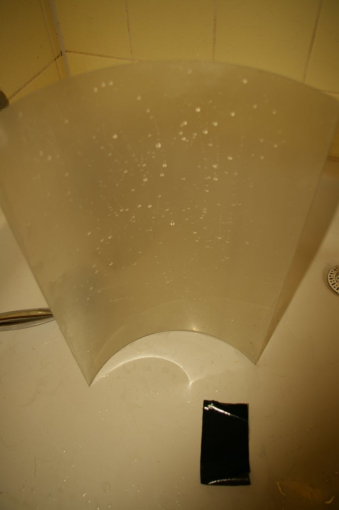
I frosted the plastic using sandpaper (Pic4-6).
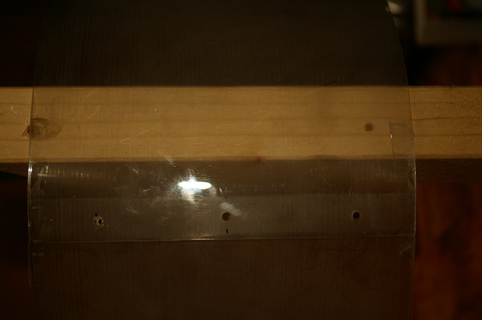
To get a smooth cylinder I screwed it all together after drilling the right holes (Pic7-8).
Mount the plastic shades on the threaded brass supports. It looks nicely and is rather easy to get and handle.
I drilled and tapped the holes to match the 1/8th threaded bar (Pic9-10).
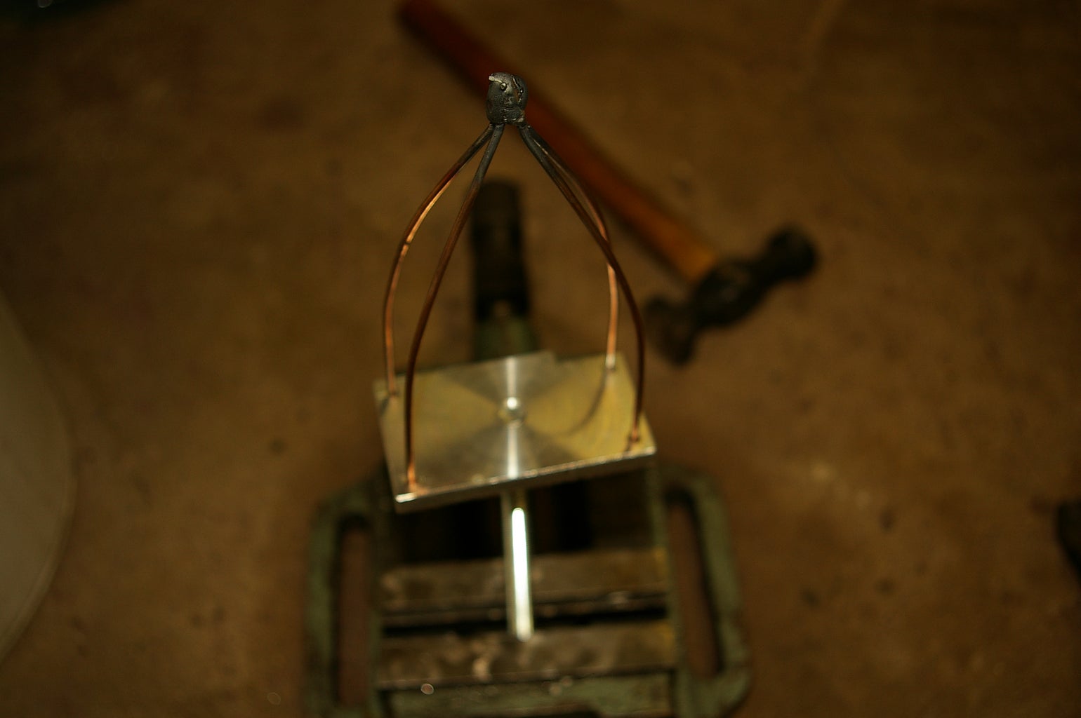
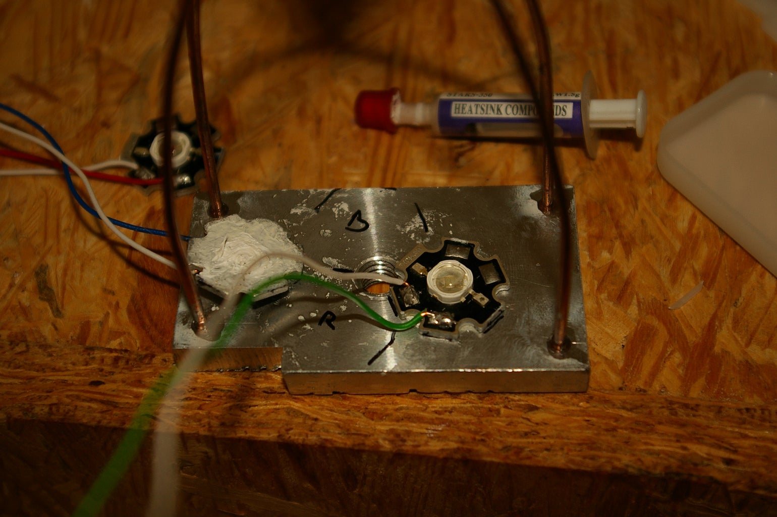
meanwhile, I made a heatsink to cool down the 3W LEDs and to have a solid base.
For getting not too many shades from the shaft, I build a little cage from welding rod with a M8 nut on top (Pic12).
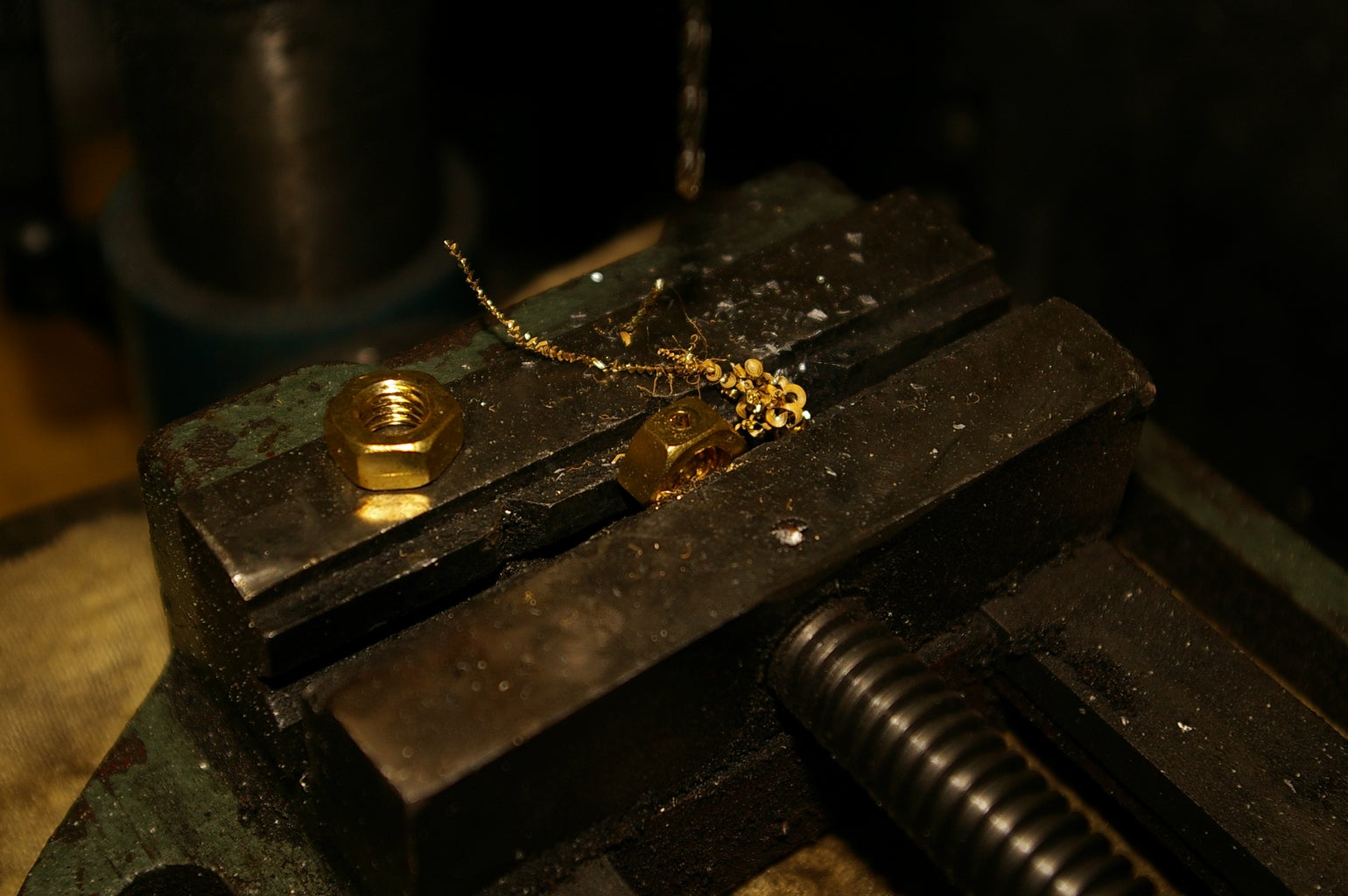
As finish i assembled all together. The little screws and nuts were a little tricky, but 30minutes later I got it done.
Step 3: The Handmade Shade

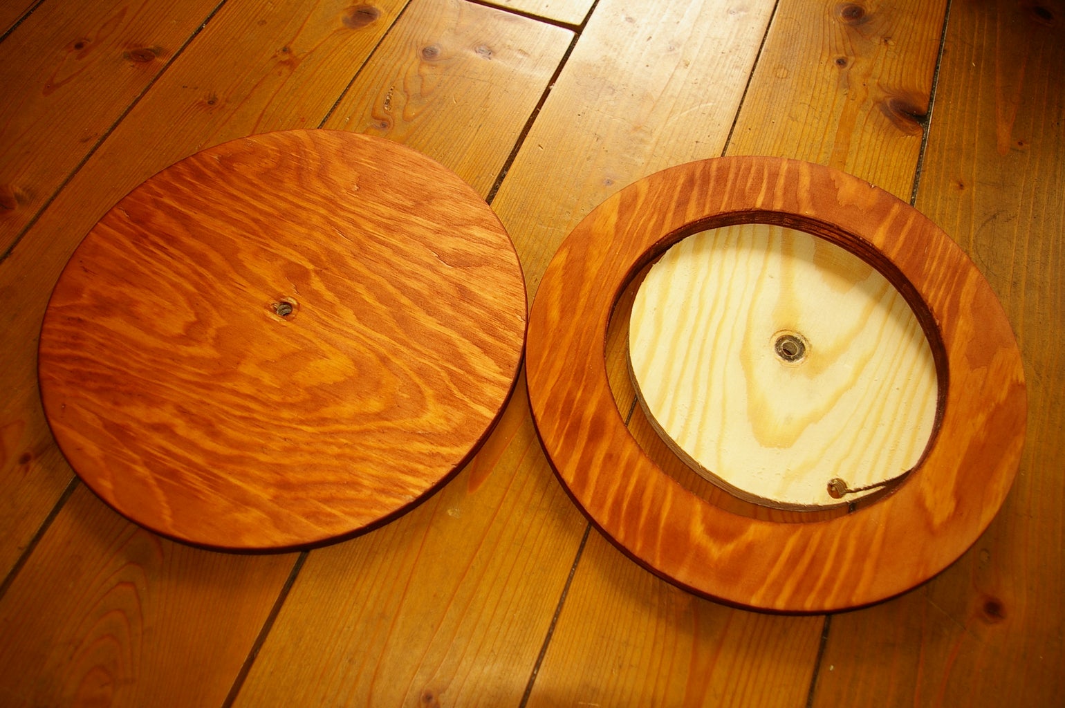

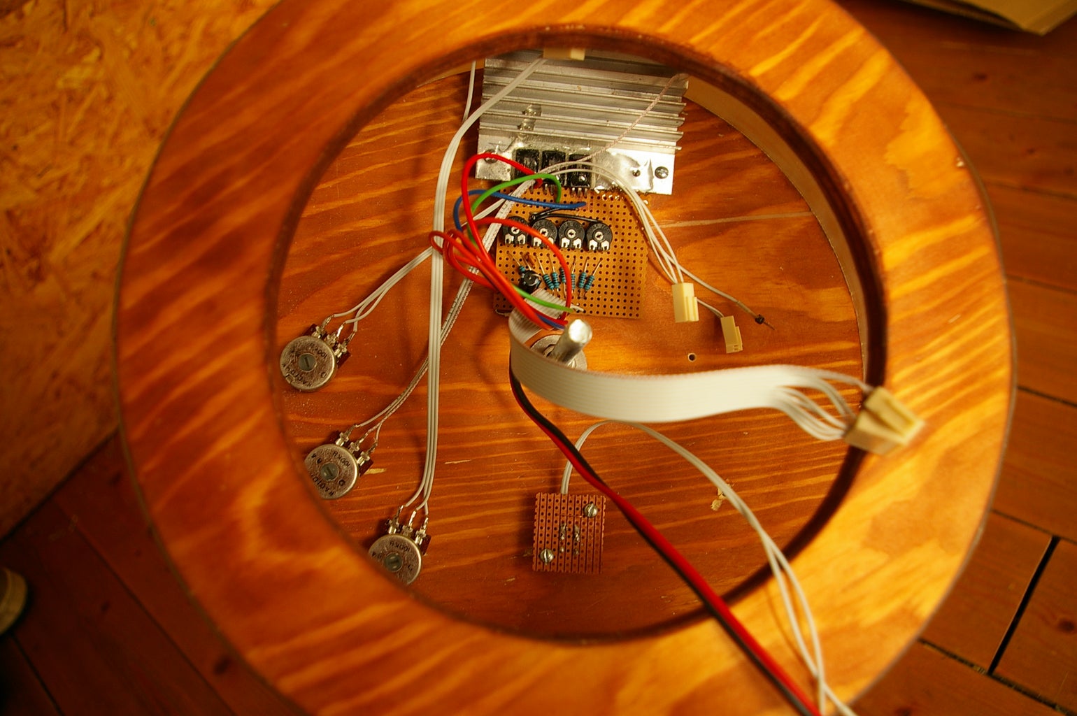
The base:
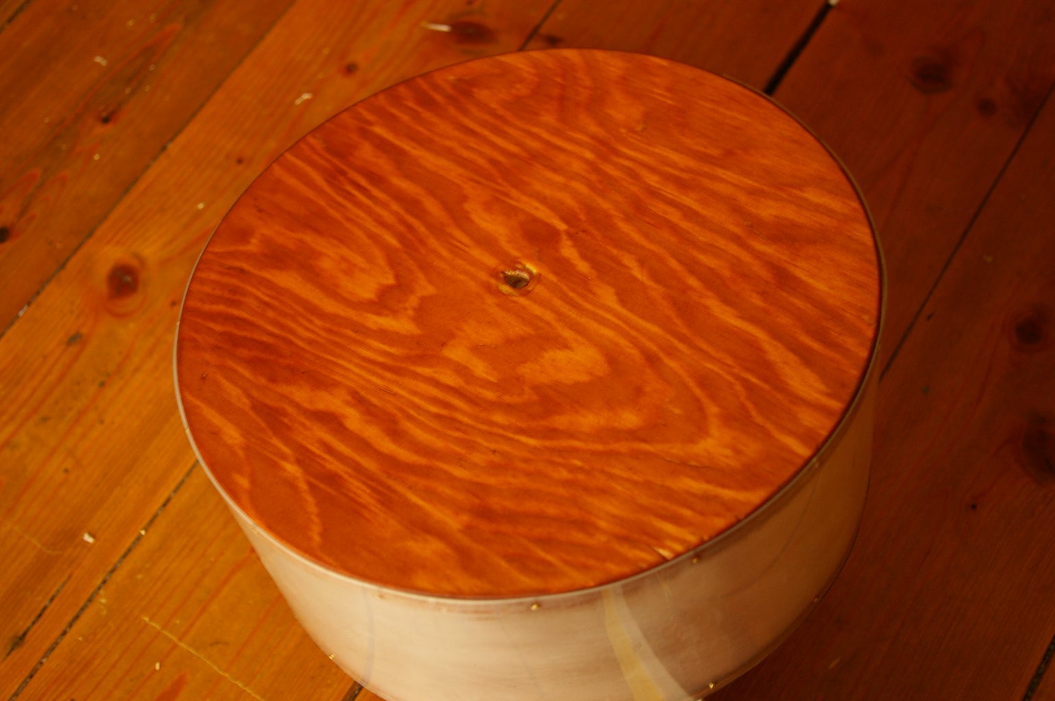
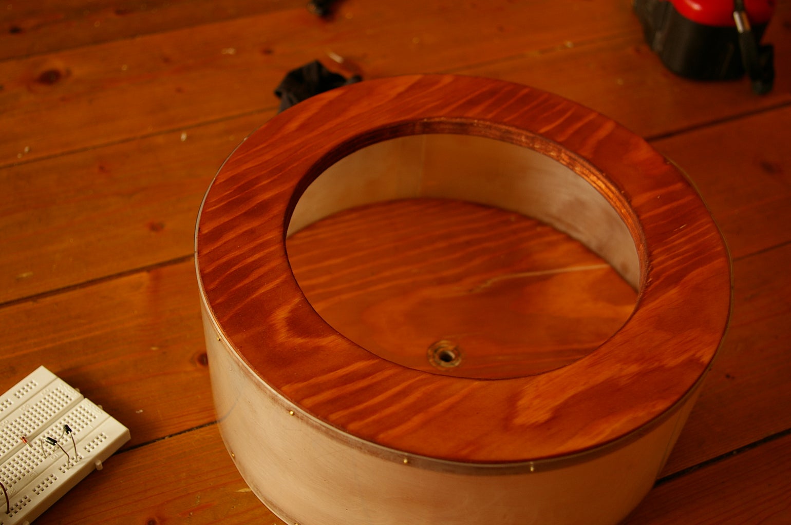
The discs were chucked in the lathe to get it smooth and round.
Afterwards, I stained it with a mahogany wood stain so the to make the pine look good.
What next?!?
I decided to make a base using the same frosted plastic as the shade, and backlight it with a RGB microLED (Pic5).
The knobs:
I made the button from a piece of mahogany and the knobs from a offcut of nutwood.
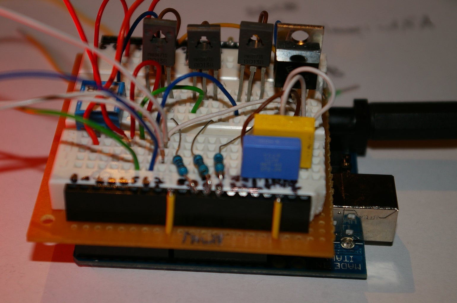
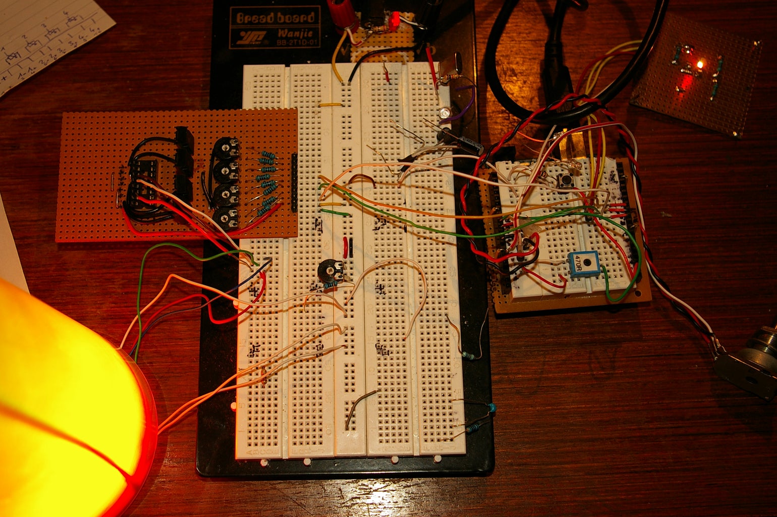
Step 4: The Electric Circuit:


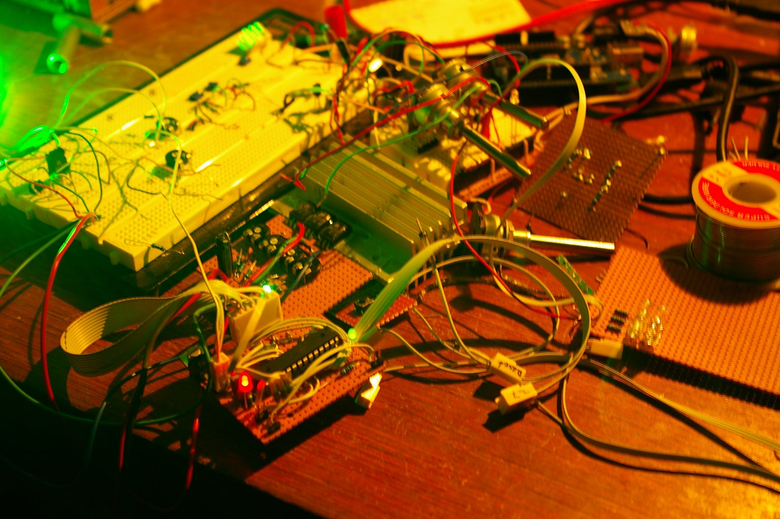
On the first picture you see my schematic.
And here's another video:
http://de.youtube.com/watch?v=xkiYzQAYf_A&NR=1
Step 5: The Code:


I started with "Spooky Projects" and "BionicArduino" by TodEKurt some months ago.
http://todbot.com/blog/spookyarduino/
My code is just a tricky combination of his project code.
"RGBMoodlight", "RGBPotMixer"
and some extensions.
Three analog-in and.
one digital-in as mode switch (Thanks to Ju. for the interrupt-routine :) .
The LEDs are connected to D9,D10 and D11 which support PulseWithModulation.
If you like, I can publish the sketch, but it's a really bare combination of these two great codes.
Here's my original code of the lamp.
It looks a little messy, because it was my very early stage in programming...
But if you copy it, it should work great.
There are fine peaces, like the "PotColorMixer", the "RGBfadingFunction" and the Interrupt-Routine for the mode-switch.
/* nejo June2008
- Code for my "Moodlamp", based on "dimmingLEDs" by Clay Shirky <clay.shirky@nyu.edu>
- Final code for the moodlamp with interrupt-mode-switch, analog speed-dial for RGB-fading and RGB color change.
- The dimming-function works just for the white color
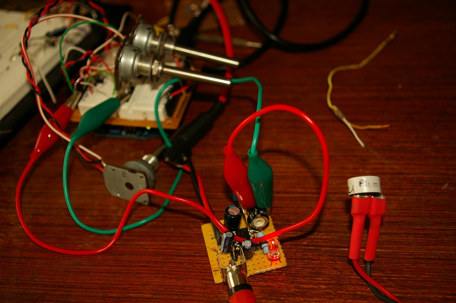
- Sound-extension for the moodlamp:
- A condensor microphone with a tiny LM368 Amp, a recifier and a RC-low-pass-filter
- with another analogInput I use the RGBPotMixer-function to change the color by getting the mic-signal.
*
*Code for cross-fading 3 LEDs, red, green and blue, or one tri-color LED, using PWM
- The program cross-fades slowly from red to green, green to blue, and blue to red
- The debugging code assumes Arduino 0004, as it uses the new Serial.begin()-style functions
- originally "dimmingLEDs" by Clay Shirky <clay.shirky@nyu.edu>
- AnalogRead is enabled on Pin A0 to vary the RGB fading speed
- AnalogRead is enabled on Pin A2 to vary the hueRGB color
*
*/
#include <avr/interrupt.h>
// Output
int ledPin = 13; // controlPin for debugging
int redPin = 9; // Red LED, connected to digital pin 9
int greenPin = 10; // Green LED, connected to digital pin 10
int bluePin = 11; // Blue LED, connected to digital pin 11
int dimredPin = 3; // Pins for the analog dimming value, connected to the transistor driver
int dimgreenPin = 5;
int dimbluePin = 6;
// Input
int switchPin = 2; // switch is connected to pin D2
int val = 0; // variable for reading the pin status
int buttonState; // variable to hold the button state
int buttonPresses = 0; // 3 presses to go!
int potPin0 = 0; // Pot for adjusting the delay between fading in Moodlamp;
int potPin2 = 2; // Potentiometer output for changing the hueRGB color
int potVal = 0; // Variable to store the input from the potentiometer
int maxVal = 0; // value to save the dimming factor default is 255, if no Pot is connected
int dimPin = 4; //Pot connected to A4 to dim the brightness
// Program variables
int redVal = 255; // Variables to store the values to send to the pins
int greenVal = 1; // Initial values are Red full, Green and Blue off
int blueVal = 1;
int i = 0; // Loop counter
int wait;// = 15; // 50ms (.05 second) delay; shorten for faster fades
int k = 0; // value for the controlLED in the blink-function
int DEBUG = 0; // DEBUG counter; if set to 1, will write values back via serial
int LCD = 0; // LCD counter; if set to 1, will write values back via serial
void setup()
{
pinMode(ledPin, OUTPUT);
pinMode(redPin, OUTPUT); // sets the pins as output
pinMode(greenPin, OUTPUT);
pinMode(bluePin, OUTPUT);
pinMode(dimredPin,OUTPUT);
pinMode(dimgreenPin,OUTPUT); // sets the pins as output
pinMode(dimbluePin,OUTPUT);
pinMode(potPin2, INPUT); //
pinMode(potPin0, INPUT); //
pinMode(dimPin, INPUT); //
pinMode(switchPin, INPUT); // Set the switch pin as input
attachInterrupt(0,isr0,RISING);
if (DEBUG) { // If we want to see the pin values for debugging...
Serial.begin(9600); // ...set up the serial ouput on 0004 style
}
}
// Main program
void loop()
{
if (buttonPresses == 0) {
Moodlamp(); // calls the Moodlight function
}
if (buttonPresses == 1) {
RGBPotMixer(); // calls the manuel mix function
}
if (buttonPresses == 2) {
White(); // It's all white in here
}
if (buttonPresses == 3) {
}
//Moodlamp();
//RGBPotMixer();
//White();
Monitor();
dim();
}
void Monitor(){ // Send State to the monitor
if (DEBUG) { // If we want to read the output
DEBUG += 1; // Increment the DEBUG counter
if (DEBUG > 10) { // Print every 10 loops
DEBUG = 1; // Reset the counter
Serial.print(i); // Serial commands in 0004 style
Serial.print("\t"); // Print a tab
Serial.print("R:"); // Indicate that output is red value
Serial.print(redVal); // Print red value
Serial.print("\t"); // Print a tab
Serial.print("G:"); // Repeat for green and blue...
Serial.print(greenVal);
Serial.print("\t");
Serial.print("B:");
Serial.print(blueVal); // println, to end with a carriage return
Serial.print("\t");
Serial.print("dimValue:");
Serial.print(maxVal); // println, to end with a carriage return
Serial.print("\t");
Serial.print("wait:");
Serial.print(wait); // writes the value of the potPin0 to the monitor
Serial.print("\t");
Serial.print("hueRGBvalue");
Serial.print(potVal); // writes the value of the potPin0 to the monitor
Serial.print("\t");
Serial.print("buttonState:");
Serial.print(buttonState); // writes the value of the potPin0 to the monitor
Serial.print("\t");
Serial.print("buttonPresses:");
Serial.println(buttonPresses); // writes the value of the buttonPresses to the monitor
}
}
}
void dim() // Function for dimming White // maybe later for all Modes
{
maxVal = analogRead(dimPin);
maxVal /= 4; // Analog range from 0..1024 --> too much for dimming the 0..255 value
analogWrite(dimredPin,maxVal);
analogWrite(dimgreenPin,maxVal);
analogWrite(dimbluePin,maxVal);
}
void Moodlamp()
{
wait = analogRead(potPin0); // look for the value from the potPin0;
// if no Pot is connected: wait 255
i += 1; // Increment counter
// i = i - maxVal;
if (i < 255) // First phase of fades
{
redVal -= 1; // Red down
greenVal += 1; // Green up
blueVal = 1; // Blue low
}
else if (i < 509) // Second phase of fades
{
redVal = 1; // Red low
greenVal -= 1; // Green down
blueVal += 1; // Blue up
}
else if (i < 763) // Third phase of fades
{
redVal += 1; // Red up
greenVal = 1; // Green lo2
blueVal -= 1; // Blue down
}
else // Re-set the counter, and start the fades again
{
i = 1;
}
// we do "255-redVal" instead of just "redVal" because the
// LEDs are hooked up to +5V instead of Gnd
analogWrite(redPin, 255 - redVal); // Write current values to LED pins
analogWrite(greenPin, 255 - greenVal);
analogWrite(bluePin, 255 - blueVal);
/* dimredVal =min(redVal - maxVal,255); //dimming
dimredVal =max(redVal - maxVal,0);
dimgreenVal =min(greenVal - maxVal,255);
dimgreenVal =max(greenVal - maxVal,0);
dimblueVal =min(blueVal - maxVal,255);
dimblueVal =max(blueVal - maxVal,0);
analogWrite(redPin, 255 - dimredVal); // Write current values to LED pins
analogWrite(greenPin, 255 - dimgreenVal);
analogWrite(bluePin, 255 - dimblueVal);
*/
wait /=4;
delay(wait); // Pause for 'wait' milliseconds before resuming the loop
}
void RGBPotMixer()
{
potVal = analogRead(potPin2); // read the potentiometer value at the input pin
potVal = potVal / 4; // convert from 0-1023 to 0-255
hue_to_rgb( potVal); // treat potVal as hue and convert to rgb vals
// "255-" is because we have common-anode LEDs, not common-cathode
analogWrite(redPin, 255-redVal); // Write values to LED pins
analogWrite(greenPin, 255-greenVal);
analogWrite(bluePin, 255-blueVal);
}
void White(){
analogWrite(redPin, maxVal); // Write values to LED pins
analogWrite(greenPin, maxVal);
analogWrite(bluePin, maxVal);
}
/*
- Given a variable hue 'h', that ranges from 0-252,
- set RGB color value appropriately.
- Assumes maxValimum Saturation & maximum Value (brightness)
- Performs purely integer math, no floating point.
void hue_to_rgb(byte hue)
{
if( hue > 252 ) hue = 252; // stetback to 252!! nejo
byte hd = hue / 42; // 36 == 252/7, 252 == H_MAX
byte hi = hd % 6; // gives 0-5
byte f = hue % 42;
byte fs = f * 6;
switch( hi ) {
case 0:
redVal = 252; greenVal = fs; blueVal = 0;
break;
case 1:
redVal = 252-fs; greenVal = 252; blueVal = 0;
break;
case 2:
redVal = 0; greenVal = 252; blueVal = fs;
break;
case 3:
redVal = 0; greenVal = 252-fs; blueVal = 252;
break;
case 4:
redVal = fs; greenVal = 0; blueVal = 252;
break;
case 5:
redVal = 252; greenVal = 0; blueVal = 252-fs;
break;
}
}
void isr0(){
Serial.println("\n \n inerrupt \n");
buttonState = digitalRead(switchPin); // read the initial state
delayMicroseconds(100000);
//if (val != buttonState) { // the button state has changed!
// if (buttonState == HIGH) { // check if the button is now pressed
buttonPresses++;
// }
// val = buttonState; // save the new state in our variable
if (buttonPresses == 3) { // zur�cksetzen
buttonPresses = 0;
}
}
// }
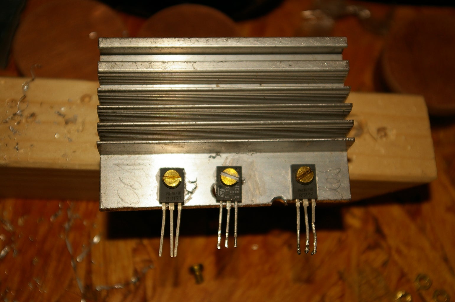
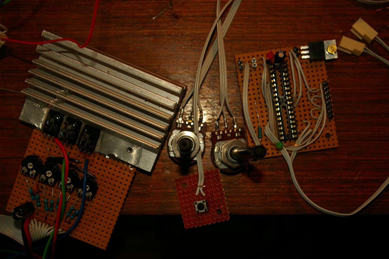
Next stage were the transistor-drivers. I used 3 PNP transistors with a maximum current on 3Ampere. After forward-current and voltage were regulated, the LEDemitter worked great with full intensity.
Step 6: Get It Standalone With PonyProg-burned Bootloader

How to use your paralell port to burn the arduino bootloader on a ATmega168 or ATmega8 to use a cheap blank chip with the arduino environment.
coming soon..... maybe on a seperate instructable
Here's also a good instructable to use the chip standalone:
https://www.instructables.com/id/uDuino-Very-Low-Cost-Arduino-Compatible-Developme/?ALLSTEPS
Step 7: So That's My Arduino Moodlamp

If you liked it, please rate me.


