

Introduction: Harbor Freight Router Speed Control Mod


Intro
The Harbor Freight Router Speed Control is a bargain-priced (on sale for $19.99, with a 20% OFF coupon, just $17.40 with the tax) general purpose electrical controller, despite its very limited name. It is widely used for controlling heating elements, motors (be careful here, it only works with certain types of motor), and high-power stage lighting, just to name a few uses. I bought one to control a popcorn popper to roast coffee. The popper was getting too hot so I needed to be able to control its temperature and had read about using this device for the purpose. You just plug in the power cord and you can use the 3-way switch for Var(iable), Off, and Full. It is spec'ed to be able to handle 15 amps (1500W).

The need to mod…
After using it several times, I decided that the chip, which is a BTA26-600B A320 Triac, was getting too hot. Touching the backplate, with the unit not even on full power, I could only stand the heat for about 2-3 seconds. This was designed to provide intermittent power to a router, not continuous power to a heating element. Even though I can replace this chip for around $2 on eBay, you never want to overdrive a component like that, so I decided to add a heatsink, like the guys who use this unit for controlling heating elements for beer brewing and controlling industrial lighting. The heatsink cost me more than a replacement chip and some time and labor but I like to 'do it right the first time' (old IBM slogan), or in this case, the second or third time ;), whenever I have the luxury to do so.
Step 1: The Mod
The heatsink
So I ordered this nice 60x150x25mm High Quality Aluminum Heat Sink for LED and Power IC Transistor H148 from eBay seller goldpart.

It took weeks to get here from China but it is a quality product and only cost me $4.49 shipped. The backplate on the controller, which serves as a poor heatsink, measures 110mm x 54mm. You can get a heatsink on eBay that closely fits those dimensions but, for a dollar more, I opted to get this oversized one.
Detach components from the backplate
I decided that the easiest way to do this was to simply detach the components from the backplate and mount them directly to the heatsink.
Upon removing the backplate's 4 screws, the first thing to do is to detach the mounted components from the backplate.

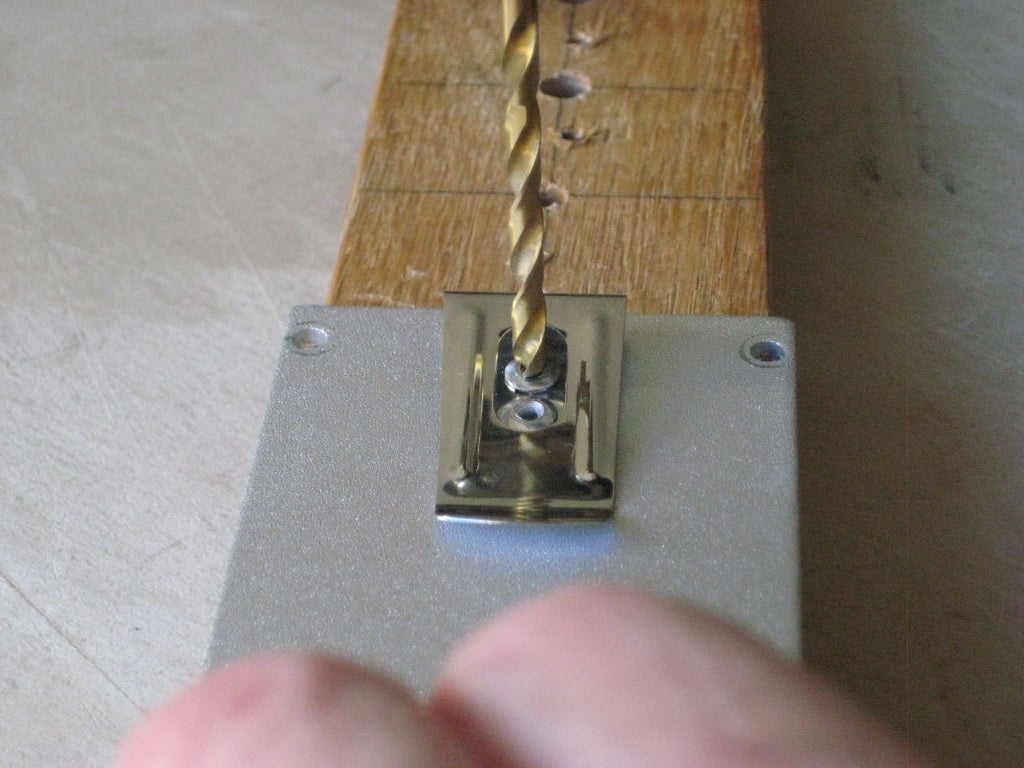
Drill out ground wire rivet
Drill out the rivet holding the 2 green ground wires. I used an electric hand drill with a 1/4" bit.
Go slowly to the point where the flange of the rivet just releases.


There was a steel or aluminum ball inside that I poked out with an awl.

Not done yet. The inside of the rivet still has the crimped sleeve attached to it. I carefully drilled that out with a drill bit that was small enough to avoid damaging the rings of the terminals on the ground wires. Probably around 1/8" but YMMV.


One terminal freed but the other one is still attached.

Easy does it.

Freed.

Unmount the triac
Remove the screw attaching the triac, with a screwdriver.

Drill out the rivets of the hanging clip
I also removed the hanging clip from the backplate so I could use the plate as a template for drilling the holes in the heatsink.

Terrible heatsink…

I was horrified to see what the manufacturer thought was a heatsink. A pebble-grained rectangle of 1/8" aluminum and NO heatsink compound! There are so many things wrong with that. First of all, a heatsink has, you know…, fins, to dissipate the heat quickly, not act as a thermal mass, building up heat to the point where it burns your fingers. Second, a heatsink is nice and smooth on the side where you mount your heat-generating component. I've even seen where over-clocking fanatics will actually lap their heat sinks with a progression of grits up to 6,000 to get mirror-finish smoothness. Over-clocking overkill to be sure but it does make the point about the requirement for smoothness. Reserve pebble-grain for leather hand bags or something else… Third, heatsink compound is absolutely mandatory to insure intimate contact between both surfaces, to promote maximum heat conduction. It fills in any micro-gaps, that surely exist on both mating surfaces, with a heat-conductive paste.
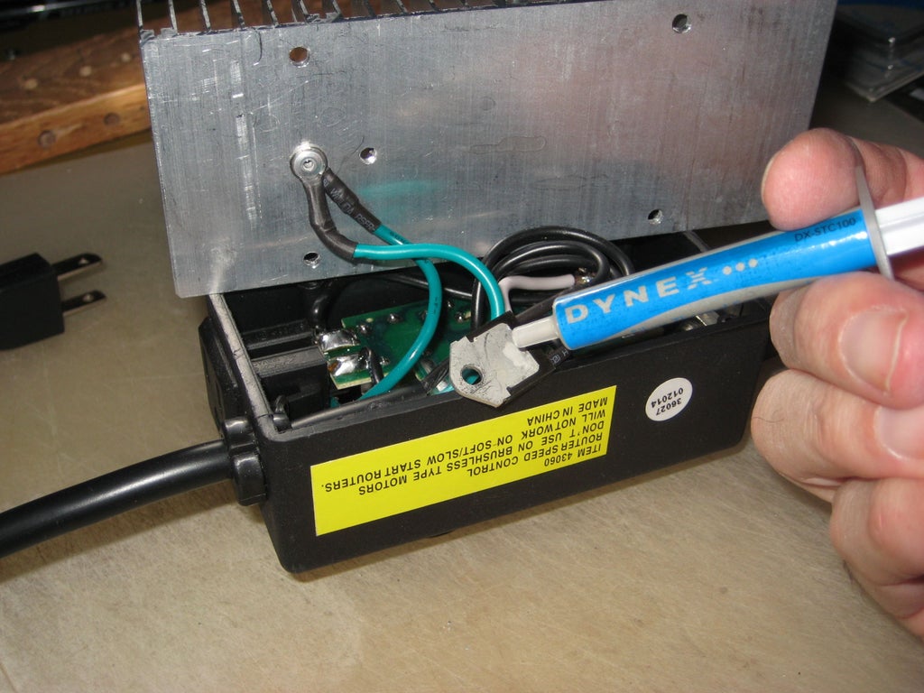
Lousy soldering job…
I was also horrified by the lousy soldering job I saw on the neutral wire direct from the wall socket.

Had to re-solder…
So the first thing I did was to re-solder it.

Not perhaps an expert job, but a lot better than it was.
Prepare the heatsink
Lay out the drill hole template
Lay out the positions of the drill holes for the mount holes and the components on the back of the heatsink. Note that the side of the backplate that was OUTSIDE the box is placed against the back of the heatsink to assure the greatest accuracy.

I first drew lengthwise guidelines by measuring the widths of the backplate and the heatsink, subtracting them and halving the remainder, and then using that value for the offset from the side edges of the heatsink. I then carefully positioned the backplate, aligning its sides with the guidelines, so that the inner edges of the mount holes just snugged up against the edge of a fin opposite them, tracing each hole with a fine permanent marker. Note that the holes for the 'bottom' (component side) are opposite the left side of the 6th fin from the left, and the holes for the 'top' side are opposite the right side of the 7th fin from the right. This was the best I could do to avoid drilling into those thick extrusions next to the fins. I drew lines under the 'inner' edges of the 5th and 6th fins and measured and marked the 'horizontal' and 'vertical' center between them for the drill hole for the 2 ground wires. I somehow messed up when drilling, and the hole ended up against the 6th fin. No biggie since I was able to get a rivet through it anyway. The hole for the triac just happened to line up with the left side of the 8th fin when the mount holes were lined up. I carefully selected a drill bit that was small enough to allow me to tap the hole for the screw.
Drill the holes
I clamped the backplate to the heatsink, being careful to line up the mount holes with the traces on the heatsink. I placed a strip of wood under the fins to avoid damaging them and rested the whole thing on 2 pieces of wood. I then drilled the 4 mount holes and the triac mount hole, using the backplate as a guide. Choose a drill bit that fits the mount holes of the backplate. Then choose a smaller bit to drill the triac hole--one that is small enough to allow tapped threads. Be sure to tap the triac hole with an appropriate size and pitch tap. You'll have to determine this on your own. I drilled the 1/8" rivet hole for the ground wires by center-punching the cross-hairs and then drilling, but my bit slipped a little as mentioned before. I couldn't use the backplate as a template because the hole would've gone right through the 6th fin.

Smooth all rough edges
Sand the cut sides and file the edges of the heatsink
I didn't take any photos of this tedious step. I first sanded the 2 saw-cut sides of the heatsink with 400 grit wet-or-dry to remove any rough spots. I removed any rough edges from the holes I drilled, both on the bottom and between the fins, with a small fine needle file. I then filed every rough edge of every fin with a small fine flat file. The tops are smooth already so didn't require filing. I beveled the sharp-pointed corners at the tips. I beveled the 4 bottom edges and the 4 corners. I went over it several times until I was satisfied it was smooth with no sharp edges or corners anywhere. Then it was ready to mount the components to.
Mount the components
Ground wires
Place a 1/8" pop rivet through the 2 ground wire terminals and into the 1/8" hole on the left. Arrange the wires so they are both down far enough to allow plenty of room for the triac.

This was the original placement:

Pop the rivet, and the wires should be firmly in place with no movement.

You could tap the hole and use a machine screw instead, if you don't have a pop rivet tool, but the Harbor Freight Hand Riveter Set is cheap ($4.99 sale price) and is a great addition to your tool collection.
Triac
Apply a generous quantity of heatsink compound to the back of the triac package.

Carefully position the triac so the holes line up.

Push down on it to start spreading the paste, and then tighten the screw firmly, but not too tight, or you could crack the plastic triac case. The paste will spread out very thinly, which is what you want--just enough to fill any gaps while maintaining as thin a layer as possible. I tapped the hole with the closest tap I had. It was off by about 1 TPI but I was able to get a good firm connection. You will have to determine the best tap to use from what you have on hand.
Put it all together
Finally, screw the heatsink in place and you are done. I had to replace the original sheet metal screws with ones that had smaller heads because the original heads were too large to fit between the fins.


Finished at last…
Here is the modified controller with the popcorn popper coffee roaster plugged in and ready to go. Even with the pot set at full power (1250W), the heatsink gets barely warm. Now I have much better control over the profile of the roast.


