

Introduction: Hardware Structure of ARDUINO UNO


Hello guys i'm glad to say that i'm back with another helpful information regarding the Arduino Uno
As i've mentioned in the previous article we came to know that there are lot of variations to experiment with Arduino types.Now we are going to lear about the hardware structure of Arduino uno.
Arduino Uno:-
The main reason to go for Arduino uno is that the UNO is the best board to get started with electronics and coding. If this is your first experience tinkering with the platform, the UNO is the most robust board you can start playing with. The UNO is the most used and documented board of the whole Arduino & Genuino family.
Step 1: OVERVIEW:-
Coming to the origin of Arduino Uno
"Uno" means one in Italian and was chosen to mark the release of Arduino Software (IDE) 1.0. The Uno board and version 1.0 of Arduino Software (IDE) were the reference versions of Arduino, now evolved to newer releases. The Uno board is the first in a series of USB Arduino boards, and the reference model for the Arduino platform.
Coming to basic outline of its specifications...
Arduino/Genuino Uno is a microcontroller board based on the ATMEGA328P. It has 14 digital input/output pins, 6 analog inputs, a 16 MHz quartz crystal, a USB connection, a power jack, an ICSP header and a reset button. It contains everything needed to support the microcontroller; simply connect it to a computer with a USB cable or power it with a AC-to-DC adapter or battery to get started.. You can tinker with your UNO without worring too much about doing something wrong, worst case scenario you can replace the chip for a few dollars and start over again.
Step 2: SCHEMATICS:-
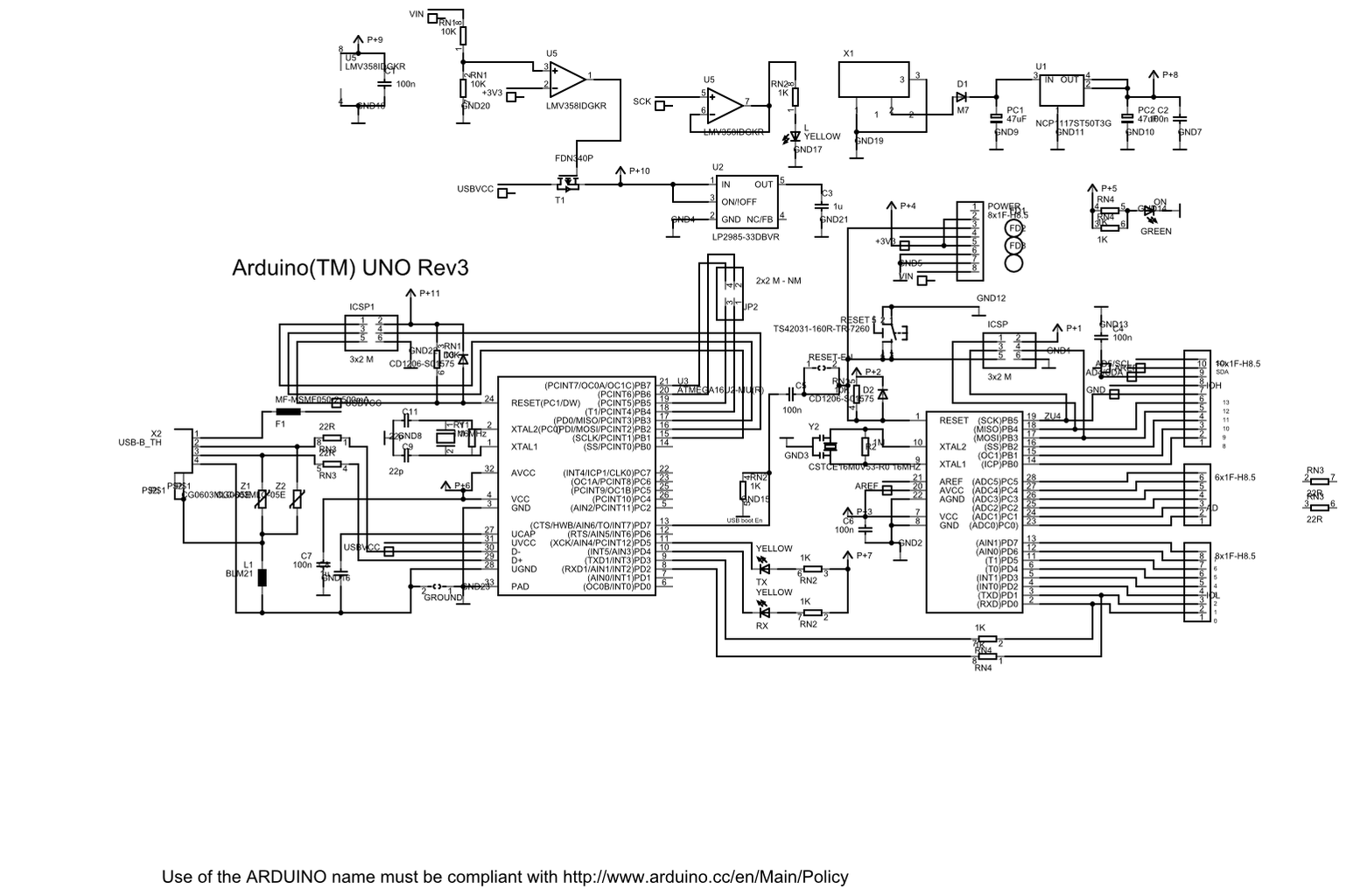
From the above Schematic we can able to get the schematic preview of how an Arduino boards are designed.
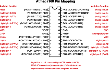
And the next pic clearly specify the pin diagram of Atmega168 Ic which is the main thing which controls the working of Arduino Uno Board.
See the mapping between Arduino pins and ATmega328P ports. The mapping for the Atmega8, 168, and 328 is identical.
Inputs and Outputs:-
Each of the 14 digital pins on the Uno can be used as an input or output, using pinMode(),digitalWrite(), and digitalRead() functions. They operate at 5 volts. Each pin can provide or receive 20 mA as recommended operating condition and has an internal pull-up resistor (disconnected by default) of 20-50k ohm. A maximum of 40mA is the value that must not be exceeded on any I/O pin to avoid permanent damage to the microcontroller.
In addition, some pins have specialized functions:Serial: 0 (RX) and 1 (TX). Used to receive (RX) and transmit (TX) TTL serial data. These pins are connected to the corresponding pins of the ATmega8U2 USB-to-TTL Serial chip.External Interrupts: 2 and 3. These pins can be configured to trigger an interrupt on a low value, a rising or falling edge, or a change in value. See the attachInterrupt() function for details.PWM: 3, 5, 6, 9, 10, and 11. Provide 8-bit PWM output with the analogWrite() function.SPI: 10 (SS), 11 (MOSI), 12 (MISO), 13 (SCK). These pins support SPI communication using the SPI library.LED: 13. There is a built-in LED driven by digital pin 13. When the pin is HIGH value, the LED is on, when the pin is LOW, it's off.TWI: A4 or SDA pin and A5 or SCL pin. Support TWI communication using the Wire library. The Uno has 6 analog inputs, labeled A0 through A5, each of which provide 10 bits of resolution (i.e. 1024 different values). By default they measure from ground to 5 volts, though is it possible to change the upper end of their range using the AREF pin and the analogReference() function.There are a couple of other pins on the board:AREF. Reference voltage for the analog inputs. Used with analogReference().Reset. Bring this line LOW to reset the microcontroller. Typically used to add a reset button to shields which block the one on the board.
Step 3: PROGRAMMING:-

Coming to its programming part.... the main thing we have to have idea is about the programming language which we are going to use for programming.
In fact, you already are; the Arduino language is merely a set of C/C++functions that can be called from your code. Your sketch undergoes minor changes (e.g. automatic generation of function prototypes) and then is passed directly to a C/C++ compiler (avr-g++).
And coming to the compiler here comes the new term called Arduino Integrated Development Board(Arduino IDE).I will discuss about its interface and complete information in my next article but now we are going for its overview.
The Arduino/Genuino Uno can be programmed with the (Arduino Software (IDE)). Select "Arduino/Genuino Uno from the Tools > Board menu (according to the microcontroller on your board). For details, see the reference and tutorials.
The ATmega328 on the Arduino/Genuino Uno comes preprogrammed with a bootloader that allows you to upload new code to it without the use of an external hardware programmer. It communicates using the original STK500 protocol. You can also bypass the bootloader and program the microcontroller through the ICSP (In-Circuit Serial Programming) header using Arduino ISP or similar; see these instructions for details. The ATmega16U2 firmware source code is available in the Arduino repository. The ATmega16U2/8U2 is loaded with a DFU bootloader, which can be activated by:On Rev1 boards: connecting the solder jumper on the back of the board (near the map of Italy) and then rese ing the 8U2.On Rev2 or later boards: there is a resistor that pulling the 8U2/16U2 HWB line to ground, making it easier to put into DFU mode. You can then use Atmel's FLIP software (Windows) or the DFU programmer (Mac OS X and Linux) to load a new firmware. Or you can use the ISP header with an external programmer (overwriting the DFU bootloader).
Step 4: POWER AND MEMORY:-

After knowing about its schematics and programming we ought to know about the Power and Memory of the Arduino Uno as power and memory are one of the main criterion to consider about the working and performance of a board
Power:-
As we already discussed the first arduino board which can be powered via a USB connection.
The Arduino/Genuino Uno board can be powered via the USB connection or with an external power supply. The power source is selected automatically.
External (non-USB) power can come either from an AC-to-DC adapter (wall-wart) or battery. The adapter can be connected by plugging a 2.1mm center-positive plug into the board's power jack. Leads from a battery can be inserted in the GND and Vin pin headers of the POWER connector. The board can operate on an external supply from 6 to 20 volts. If supplied with less than 7V, however, the 5V pin may supply less than five volts and the board may become unstable. If using more than 12V, the voltage regulator may overheat and damage the board. The recommended range is 7 to 12 volts. The power pins are as follows: Vin. The input voltage to the Arduino/Genuino board when it's using an external power source (as opposed to 5 volts from the USB connection or other regulated power source). You can supply voltage through this pin, or, if supplying voltage via the power jack, access it through this pin.5V.This pin outputs a regulated 5V from the regulator on the board. The board can be supplied with power either from the DC power jack (7 - 12V), the USB connector (5V), or the VIN pin of the board (7-12V). Supplying voltage via the 5V or 3.3V pins bypasses the regulator, and can damage your board. We don't advise it.3V3. A 3.3 volt supply generated by the on-board regulator. Maximum current draw is 50 mA.GND. Ground pins.IOREF. This pin on the Arduino/Genuino board provides the voltage reference with which the microcontroller operates. A properly configured shield can read the IOREF pin voltage and select the appropriate power source or enable voltage translators on the outputs to work with the 5V or 3.3V.
Memory:-
The ATmega328 has 32 KB (with 0.5 KB occupied by the bootloader). It also has 2 KB of SRAM and 1 KB of EEPROM
Step 5: COMMUNICATION:-

For any programmable board the next thing which is to be considered is the mode of communication with external device to recieve sketches(program given to execute).
Coming to Arduino Uno board......
Arduino/Genuino Uno has a number of facilities for communicating with a computer, another Arduino/Genuino board, or other microcontrollers. The ATmega328 provides UART TTL (5V) serial communication, which is available on digital pins 0 (RX) and 1 (TX). An ATmega16U2 on the board channels this serial communication over USB and appears as a virtual com port to software on the computer. The 16U2 firmware uses the standard USB COM drivers, and no external driver is needed. However, on Windows, a .inf file is required. The Arduino Software (IDE) includes a serial monitor which allows simple textual data to be sent to and from the board. The RX and TX LEDs on the board will flash when data is being transmitted via the USB-to-serial chip and USB connection to the computer (but not for serial communication on pins 0 and 1).
A SoftwareSerial library allows serial communication on any of the Uno's digital pins. The ATmega328 also supports I2C (TWI) and SPI communication. The Arduino Software (IDE) includes a Wire library to simplify use of the I2C bus; see the documentation for details. For SPI communication, use the SPI library.
Step 6: Warnings,Differences and Revisions:-

Warnings:-
The Arduino/Genuino Uno has a resettable polyfuse that protects your computer's USB ports from shorts and overcurrent. Although most computers provide their own internal protection, the fuse provides an extra layer of protection. If more than 500 mA is applied to the USB port, the fuse will automatically break the connection until the short or overload is removed.
Differences with other boards:-
The Uno differs from all preceding boards in that it does not use the FTDI USB-to-serial driver chip. Instead, it features the Atmega16U2 (Atmega8U2 up to version R2) programmed as a USB-to-serial converter.
Revisions:-
Revision 3 of the board has the following new features:1.0 pinout: added SDA and SCL pins that are near to the AREF pin and two other new pins placed near to the RESET pin, the IOREF that allow the shields to adapt to the voltage provided from the board. In future, shields will be compatible with both the board that uses the AVR, which operates with 5V and with the Arduino Due that operates with 3.3V. The second one is a not connected pin, that is reserved for future purposes.Stronger RESET circuit.Atmega 16U2 replace the 8U2.
Step 7: TECHNICAL SPECIFICATIONS:-

The above table describes the technical specifications of Arduino Uno at a Glance...........
Hope you all got an idea about Hardware and Technical Specifications of Arduino Uno
See you again in next article....


