

Introduction: Harry Potter Inspired Weasley Clock


Last year I decided to reread the entire Harry Potter series for the 100th time, which inspired the idea to make something like the Weasley family clock for a class final project. For all you muggles who aren't familiar with the series, the wizarding family of Weasleys has a rather unusual clock - instead of showing the time of day, it shows where each member of the family is located at that moment. Since it's not obvious from the photo how big the clock is (it's about 5' tall), I've asked Professor Snape to model for scale.
My goal initially was to create such a clock that would show my location by using my phone to send GPS signals to a wifi device on an Arduino. As it turned out, there's actually someprojects that already have figured out the software and electronics to track the user's location using different methods. Since I only had a week and a half to make the project, I decided instead to focus on designing a really cool clock body, particularly since I was excited to get more experience using a CNC router. The design I drew features Hogwarts at the bottom and the four Marauders at the top.
This Instructable will show you how you can build the hardware for this clock (the clock body, the clockwork, and the electronics). It will not show you how to do the software, as I wound up manually controlling the clock from my computer so get it wrapped up in time for the final, but if you (or your house elf) do manage to finish the programming, I'd love to see what you did!
One last note before we start: I consider the clock I made as more of a 1st iteration/prototype since I made a few machining errors, and the wood I used has a terrible surface finish. The photo at the top is untreated plywood, but I imagine it would like far nicer with varnished or dyed wood!
Step 1: Tools & Materials
Tools:
CNC Router
Laser Cutter (optional, you could probably use a router as well)
3D Printer (optional, you could buy the parts you need to print)
Materials:
Many of the materials choices are flexible and can be swapped out with something similar. I'll talk about the exact materials I used as I get to each section, and you can decide if you want to modify the model based on what you have on hand.
2'x5'x3/4" plywood
2'x5'x1/4" plywood
1/4" Acrylic sheet
1-2 Ball bearings (I found some for free that were 5/16" ID, 11/16" OD)
Fasteners (bolts, nuts, etc.), around 1/8-3/16" diameter, 2" and 1" long
Plastic spacers (around 0.4")
Gears (or you can be lazy and 3D print them like I did, .stl files are included)
A servo (I used this one)
Electronics:
I made my own PCB but it's probably easier to just use an Arduino or Raspberry Pi. However, if you decide to make your own PCB you'll also need:
Desktop CNC Mill
PCB Board stock
Electronic components (details in the Eagle file)
Arduino compatible WiFi shield (I used this one)
Optional:
Wand (suggested incantations are included in the instructions)
Step 2: Files
There's a whole lot of files that go along with this Instructable, so I'm including them in their own section.
.stl Files:
This is pretty much the entire clock in .stl files, divided up into the clockwork, the body, and the clockface. Hopefully it should be clear how everything assembles from full_model.stl, but let me know if you have any questions. If you need the file in another format (the originals are all Solidworks files) let me know.
Electronics:
If you want to try your hand at making your own microcontroller, I've also attached the EAGLE* files for the board.
*EAGLE as in the program, not showing any bias to Ravenclaw, I promise. Anyway, I was sorted into Hufflepuff on Pottermore. I commenced to delete my account and pretend it never happened.
(Note: I didn't make the .stl model for the servo, I got it from grabcad.com)


Step 3: The Clockwork Assembly


Materials & Files:
clockwork_plate.stl (x3): laser cut out of 1/4" acrylic, although any structural material will work
clockwork_servogear.stl: 3D printed or purchased
clockwork_gearshaft.stl: 3D printed or purchased
Servo
Spacers (x12) (I just found some free ones lying around, so the size is pretty flexible)
Fasteners
Bearings (2 pictured but I wound up only using one)
The clock is run by a servo, since it's an easy way to specify what angle the hand needs to point at (and I had a free servo). However, since most servos only go 180 degrees, I used a 2:1 gear train to make the hand go a full 360. The smaller gear is attached to the axle connected to the clock hand, and the larger is on the servo.
I didn't have time to buy any gears (and for whatever reason, the summoning charm was failing me), so I wound up 3D printing the gears. If you choose to buy some, keep in mind that the number of gear teeth doesn't matter as long as you maintain the 2:1 ratio. You could probably also slim the clockwork down by using thinner metal gears.
I decided to 3D print the gear and the axle for the clock hand in one piece, although if you don't have access to a 3D printer. A plastic 3D printed axle isn't especially structural but since the only load it has to bear is the clock hand (which was made of acrylic), 3D printing was good enough for my purposes. If you go with a heavier clock hand, you probably want to use more structural axle made of metal or wood, and match the bearing size appropriately. Alternatively, you could try using a simple levitation charm (the incantation is Wingardium Leviosa) to take the weight off the axle.
For the gear that is attached to the servo, it's designed so I could take one of the plastic "arms" that comes with the servo, cut off the arm, and press fit the remaining part into my gear.
I laser cut the flat plates of the assembly. There's three of them, though you could remove the back plate if you aren't worried about exposing the gears. Note for the plates it's just the same thing cut file three times, and then assembled using some bolts and spacers. Depending on the servo, bearings, and fasteners you use, you may need to enlarge/shrink some of the holes (the incantations are "Reducio" and "Engorgio" respectively, but careful not to wave your wand to much or the holes will be huge).
Note that the bearings are press fit directly into the plate and the axle shaft. Since every laser cutter is different, you made need to make a few test cuts with your laser cutter to figure out the best diameter for the fit.
Although there are two bearings pictured, I only wound up using one since the axle wasn't bearing much load and it was much easier to dissamble my clockwork assembly (since the bearing is press fit both onto the axle and into the acrylic plate).
Step 4: The Clock Body


Materials & Files:
Wood (I used plywood)
body.stl
body_frame.stl
body_moony.stl
body_prongs.stl
body_padfoot.stl
body_wormtail.stl (I really wanted to get rid of him because he's traitorous jerk, but they wouldn't be the Marauders without him...)
The design of clock body was inspired by the shape of a grandfather clock, but with a bit of a twist to make it feel more "magical". (Someone pointed out to me later on it's also a bit reminiscent of a coffin shape... whoops...) I wanted to mount it directly on my wall, so I tried to keep the whole thing thin. However, I can imagine if you want this to look even more like a grandfather clock, you could make it have a more 3-dimensional shape, or add a base.
The clock body (not including the clock face) was made in two parts. The first is a 1/4" piece of plywood that provided the top layer. The second is a 3/4" part for the bottom layer. I used a CNC Router (a ShopBot) to route both pieces.
The thinner top part is just a 2D profiling cut.
For the thicker layer, I wanted it to have a bit of a sculpted shape, so many of the edges are filleted. I did a rough 2D pocketing cut using a 1/4" end mill. Then I did the finish as a 2.5D cut with a 1/8" end mill. Even with the 1/8" end mill, the surface finish was pretty poor (and it took about 3 hours to complete - I wound up having to use a time-turner to get the project finished in time!). The bad finish came from a few factors: the Shopbot software I had access to only rasters, I didn't have a downcutting end mill (you'll get much cleaner cuts since it won't pull up the wood), and plywood is not a great material. If I make this again, I'll probably abandon the 3D finishing cut and just sand down the edges instead to get the bevels. I'll also use solid wood instead of plywood for a nicer finish.
The top and bottom pieces were assembled with wood glue, and some clamps and weights while it dried. You'll notice in the final version there's a weird "step" at the top - that's because I accidentally resized one of my files and didn't realize it until I went to glue the pieces together!
Step 5: The Clock Face

Materials & Files:
1/4" Acrylic sheet (wood, metal, MDF, etc. would also work)
clockface_clockhand.stl
clockface.stl
clockface_backcircle.stl
I had several people ask me if the clock face is metal. Nope, it's not. It's just acrylic spray painted silver. You could probably use wood or any other material. Or if you're really cool and have access to a water jet, you could make the clock face out of aluminum or steel!
The back circle attaches to the clockwork in the back, and then is bolted to the clock face in the front, and then the clock hand is then bolted to the gear axle. I'd been thinking of putting in LED's behind the clock face to back light it (which is why I left so much space back there), but in the end I thought it would look too cheesy.
I cut all the pieces on a laser cutter. You could also try to cut it with Sectemsempra, but it could be messy.
If you want to make or modify the clock face, the font I used can be found here.
Step 6: Electronics


Materials & Files:
Eagle fabduino files
PCB board stock & componenets
WiFi shield
As mentioned earlier, my original goal was to send GPS coordinates from my phone to a webserver, pull that data with a WiFi enabled microcontroller, and use that to control the servo.
Phone --> Webserver --> WiFi enabled microcontroller --> Move that servo!
The current clock is just controlled from my computer. However, I'm including the instructions for the electronics for anyone who feels like trying their hand at making their own PCB. If you're fairly new to electronics I would skip this section since it's filled with a lot of jargon like "MOSI", "SCK", and "Riddikulus".
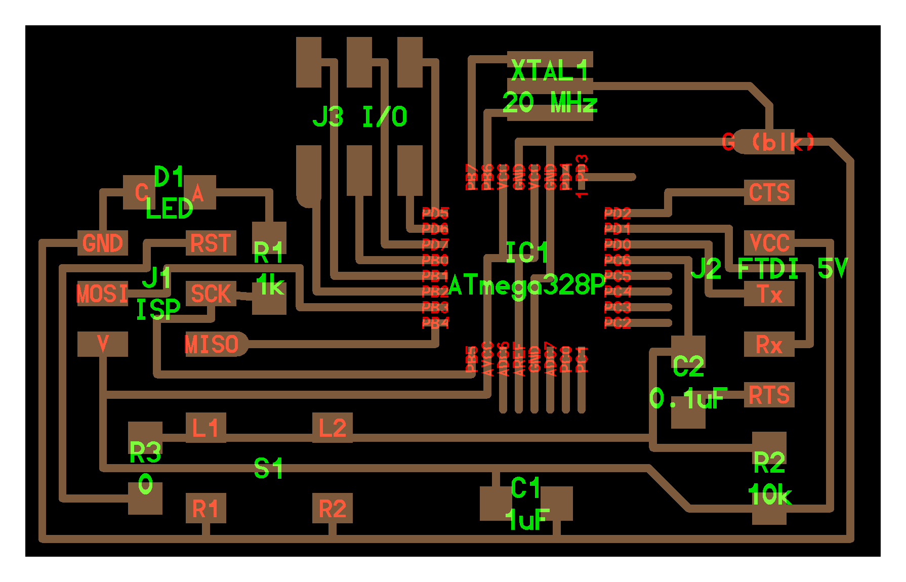
Because all the libraries for the WiFi module I had are made for an Arduino it made the most sense for to use an Arduino as my microcontroller. Enter the Fabduino! The Fabduino is basically a DIY Arduino, and it's awesome. With the Fabduino, you can program the WiFi shield as though it's attached to an Arduino. There's already some great documentation online, including The Fabkit and Neil Gershenfeld's board.
For designing my own board, I made some modifications to the existing boards:
- Removing any pins I wouldn't need for the servo or WiFi Shield. (I left an extra set of pins for a second servo, in case I decide to add another clock hand later on)
- Adding a voltage regulator and a power jack for external power
- Adding resistors to the MOSI/MISO/SCK pins that will be used by both the ISP programmer and the WiFi Shield, and a pull up resistor to the CS pin
- Using an ATMega328p on my board rather than the 168, since that was in the inventory I had access to.
- Using a 20MHz Resonator, instead of 16MHz resonator since that's what I had on hand (I made a second board later in which I believe I used the 16MHz)
If you want to modify the Fabduino further, take a look at the documentation on the WiFi Shield.
Or, if you prefer to go the magical route, try using a "Point Me" charm instead.
Step 7: Software


Because my focus for my project was on the hardware, I didn't get around to finishing the software. I'm including the documentation in case anyone decides to try to take this route for the programming. However, there's probably more efficient ways to achieve the same results.
Being a mechanical engineer, I'm a little bit of a squib when it comes to some of this stuff. Fortunately for me, my friend Zach has a lot of experience in creating iPhone applications, so he helped me with this part of the project. We decided to start by manually sending the location to a webserver before trying to figure out GPS. To do that, we wrote a really simple iPhone app in XCode (you can see we only have some buttons for testing purposes).
Then, we used Parse as a way to send and store the data. Parse allows you to write data to a table stored on their webservers. You can see in screenshot below that it stores the location. We wrote it so that it updates the location rather than adding more rows to the table, but that would be possible as well.
From there, we wrote a really simple test website using HTML and Javascript. The URL is: http://web.mit.edu/jasminef/Public/Clocksite/index.html. You'll notice if you click on it, the URL will be appended by a location tag like #MORTAL_PERIL or #LAB. We were trying to pass information to the microcontroller via the URL (we also tried writing directly to website).
Unfortunately, what we didn't take into account was the fact that the microcontroller doesn't process javascript. So when we tested reading the data in using an Arduino and a WiFi shield, what we found was that the WiFi shield read the HTML code but didn't run the javascript. If you do choose this route, there are ways to get the Arduino to process javascript.
Step 8: Mischief Managed!
That's about the sum of it! From other tutorials online, you can figure out a way to actually get realtime GPS data to give the location on the clock, but hopefully this tutorial will help you build a cool clock body. If you have any questions about building the clock, don't hesitate to ask.
Lastly, mischief was only managed with the help of a lot of really awesome people - my friend Zach and the TA's of MIT's How to Make (Almost) Anything course.

Participated in the
Full Spectrum Laser Contest 2016

Participated in the
Plywood Contest


