

Introduction: High Voltage Power Supply From Laser Printer


Laser Printers are treasure troves of electronic goodies from gears to lasers to high voltage power supplies. High voltage is required in laser printing to create electrostatic charges to determine where the toner sticks, creating letters and images on paper. However, modern laser printers with their power saving designs and multiple safety features makes the power supply unusable unless connected to the cpu on the laser printer itself. Today, I will be showing you how you can trick the power supply into giving out juicy high voltage with just a bit of soldering.
SAFETY: Do not touch the circuit board when it is connected to mains voltage. Many heatsinks are live and will give you a dangerous and nasty shock from the mains. This is even deadlier than the high voltage produced by the power supply.
The printer i will be using is a SAMSUNG ML-1670. Its power supply outputs 4 different voltages.
1)Transfer High Voltage (THV+)
- Input Voltage : 24 V DC ± 15%
- Output Voltage : THV+: max +3.5kV ± 10 %,(Duty Variable, no loading ) @ 6.5uA
THV-: -1kV±20% (when cleaning,200 ㏁)
- Output Voltage Control Method : Transfer Output Voltage is outputted and controlled by changing Duty of
THVPWM Signal.
2) Charge Voltage (MHV)
- Input Voltage : 24 V DC ± 15%
- Output Voltage : -1.0KV ~ -1.8KV DC ± 3% @ 26uA
- Output Control Signal(MHV-PWM) : CPU is HV output when PWM is Low
3) Developing Voltage (DEV)
- Input Voltage : 24 V DC ± 15%
- Output Voltage: -200V ~ -500V DC ±3% @ 8.6uA
- Output Loading range : 10MΩ ~ 1000 MΩ
- Output Control Signal (BIAS-PWM) : the CPU output is HV output when PWM is low.
4) Supply
- Output Voltage : -350 V ~ -650V DC ±50 V(ZENER using, DEV ) @ 11.6uA
- Input contrast of the output stability degree : under ± 5 %
- Output Loading range : 10 MΩ ~ 1000 MΩ
- Output Control Signal (BIAS-PWM) : the CPU is HV output when PWM is low.
Step 1: Gather Your Materials

Tools for tearing the printer apart
-Phillips head screwdriver
-Flathead screwdriver for prying plastic joints apart
Tools for soldering
-Soldering iron
-Solder
-Short lengths of thin wire about 30 gauge (can be harvested along the way)
Step 2: Basics Before We Start
The Power supply only outputs high voltage when we provide the correct pins on the controlling IC with the correct voltage. Under normal circumstances, the CPU gives a voltage of 3.3V to the controlling pins to turn off the high voltage power output. We need to make the voltage on these controlling pins low (GND voltage) so that the high voltage power outputs are turned on.
In summary
When control voltage is HIGH (3.3V), then HV output is OFF
When control voltage is LOW (GND), then HV output is ON
The power supply can only work when the CPU board is connected
Disconnecting the CPU board from the power supply doesn't work either, there are other pins giving ON instructions to the power supply from the CPU.
Our solution is to cut out the copper traces from the CPU to the controlling pins, then solder wires from GND to the controlling pins. This is all done while leaving all other pins intact. The power supply will be tricked into thinking that the CPU is instructing it to turn on the high voltage.
The are 3 controlling pins we need to solder to.
PWM DEV
PWM MHV
PWM THV
WE WILL NOT TOUCH THE CPU BOARD, it is too complicated and totally unncessary.
Step 3: Find the CPU Board and Power Supply


The Power supply board should have many high voltage capacitors on it and should be connected to the mains.
The CPU board should be connected to the Power Supply board by a ribbon cable. (SEE PICTURE)
DIsconnect all other wires to the CPU board and leave only the Power supply ribbon cable connection.
Step 4: Find the Pins and the Switch

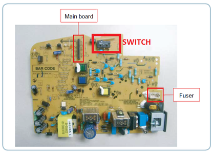
The power supply board will have markings on both surfaces to indicate which pin does what. Find the 3 pins
PWM_DEV
PWM_MHV
PWM_THV
Also find the switch on the power supply board that closes when the cover of the printer is closed. This is a safety feature such that the power supply can only output HV when the cover is closed. We will be soldering a wire to bypass this switch in the next step.
Step 5: Soldering Time.


THE PINS
1) Locate the copper traces to the 3 PWM pins on the solder side of the power supply circuit board.
2) Use a knife to scratch out a line to cut off the copper traces from the CPU ribbon cable to the controller IC (SEE PICTURE)
TIP: Try to cut the copper trace as far away from the controller IC as possible to leave some copper trace to the Controller IC for you to solder on to later
3) Use a flat head screwdriver or small piece of sandpaper to CAREFULLY scratch off the solder resist on the remaining copper trace.
4)Solder a wire to the 3 exposed copper traces
5)Find a GND connection(usually labelled for you)
6)Solder the other end of the wire to the GND Connection.
THE SWITCH
1) Short the switch pins together with a wire, this should be very simple.
Step 6: Find the High Voltage Outputs


In this printer design, almost all the action happens in the toner refill cartridge. (BLUE OBJECT IN PICTURE). The circuit board is mounted at the side vertically so that the high voltage outputs touches the contacts on the cartridge directly without a need for thick high voltage wires.
In this power supply board, the outputs are clearly labelled as DEV, MHV, SUPPLY and THV. If yours does not have such labelling, try to figure out where the "developing" stage of the printer is located, then find any wires or metal contacts that are touching the power supply. The high voltage ground contact should look the same (usually located at the periphery of the board surround everything).
At this point if you dont understand why you need a high voltage ground, you probably shouldnt be playing with HV. All the voltages output are relative to the GROUND. You will need both a HV ground and a HV output for whatever HV fun you want.
NOTE: The HV outputs are all DIRECT CURRENT.
Step 7: Reconnect the CPU Board and Power Up

1) Plug in the cpu board. Notice that we have not done ANYTHING on the cpu board. Most of the things are SMT and multilayer and it would be unwise to screw around with it.
You DO NOT need to plug in anything else such as the fuzer or motor controls.
2) Plug it into mains and turn it on.
Your indicator leds should flash and indicate normal working condition.
3) Test the high voltage outputs with your fingers.
JUST KIDDING! You will probably not die but you will seriously regret doing it.
You can use wires to connect a high resistance resistor from the HV GROUND and see if there are tiny sparks that fly from the resistor to the high voltage output.
YOU SHOULD KNOW WHAT TO DO WITH THIS PROJECT AT THIS POINT IN TIME. That is the purpose of you starting on this instructable. Power a nixie clock, charge some HV caps, whatever!
Thank you and I hope you have fun.


