

Introduction: HobbyCNC 4-Axis Stepper Motor Driver Board


Build your own high-current 4-axis stepper motor controller board for your DIY robot, DIY mill or mill conversion, DIY router or anything else that needs to move. This is a build-it-yourself kit from HobbyCNC.com.
Step 1: Inspect the Components

Open the kit and verify all parts are present. If necessary, use an ohm meter to verify the resistor values.
NOTE: This photo shows the 4-Axis Kit - the 3-Axis kit has fewer parts (only the ones required to drive the 3-axis - compare the parts count against the included printed instructions)
Step 2: Insert (8) 10k Resistors

Insert the (8) 10K (R1, R2, R3, R4, R5, R6, R7, R8 Brown Black Black Red Brown) resistors. Simply bend the leads over to fit the PCB holes (typically .400”) and solder in. We ALWAYS use an Ohmmeter to verify values before soldering in place. Trim the leads.
Step 3: Insert (4) 100k Resistors

Insert (4) 100K resistors (R9, R10, R11, R12 Brown Black Yellow Gold). Trim the leads
Step 4: Insert (2) 249 Ohm Resistors

Insert (2) 249R resistors (R13, R14 Red Yellow White Black Brown). Trim the leads.
Step 5: Install (1) 6.04k Resistor

Install (1) 6.04K (R15 Blue Black Yellow Brown Brown) resistor. Trim the leads.
Step 6: Install (1) 750 Ohm Resistor

Install (1) 750R (R16 Violet Green Black Black Brown) resistor. Trim the leads.
Step 7: Install (7) .1uF Capacitors.

Install (7) .1uF (C1, C2, C3, C4, C5, C6, C7) Capacitors. These have NO orientation. Trim the leads.
Step 8: Solder in (5) 10K Resistor Networks

Solder in (5) 10K resistor networks (RN1, RN2, RN3, RN4, RN5). Orient the dot with the PCB silkscreened dot. Trim the leads.
Step 9: Solder in (8) BS250P Mosfets

Solder in (8) BS250P Mosfets (Q1, Q2, Q3, Q4, Q5, Q6, Q7, Q8) Orient the case as shown on the PCB silkscreen. Spread the leads apart to fit the PCB holes. Trim the leads.
Step 10: Insert (4) Capacitors 10uF 50V

Insert (4) Capacitors 10uF 50V (C8, C9, C10, C11). Orient the longest lead into the hole marked “+”. The body has “-“ marked on it to help identify the proper orientation. Trim the leads. Do not confuse with C15-C18.
Step 11: Insert (4) Capacitors 100uF 16V

Insert (4) Capacitors 100uF 16V (C15,C16,C17,C18) solder in now. Orient the longest lead into the hole marked “+”. The body has “-“ marked on it to help identify the proper orientation. Trim the leads.
Step 12: Install (4) Potentiometers

Install (4) Potentiometers (VR1, VR2, VR3, VR4) now. Trim the leads.
Step 13: Solder the 2 X 4 Header Pins

Insert the 2 X 4 (J1, J2, J3, J4) Header Pins. (Installing the Jumper/Shunts onto the pins makes holding them in place easier!)
Step 14: Install P1 DB25 Male Connector

Install P1 DB25 Male connector. Take your time as many pins are close together. We also solder the mounting lugs for an even more robust mounting.
Step 15: Install the 6 Position Terminal Blocks

Install the 6 Position Terminal Blocks (TB1, TB2, TB3, TB4, TB5). Orient the holes for the wires facing “out”. These may require a little extra heat to flow the solder as a lot of copper is present.
Step 16: Install the 2 Position Terminal Blocks

Install the 2 Position Terminal Blocks (TB6, TB7) . Orient the holes facing “out”. These may require a little extra heat to flow the solder as a lot of copper is present.
Step 17: Install the LM317HV

Install the LM317HV (U7), NOT the LM317, is next to be soldered in place. Orient the tab towards R15. The PCB silkscreen shows this as a wide white band. Trim the leads.
Step 18: Install the LM317

Install the LM317 (U5). Orient the tab towards R13. The PCB silkscreen shows this as a wide white band. Trim the leads.
Step 19: Insert the 7824

Insert the 7824 (U6). Orient the tab towards C6. The PCB silkscreen shows this as a wide white band. Trim the leads.
Step 20: Install (3) 680uF Capacitors

Install (3) 680uF Capacitors (C12, C13, C14). Orient the long lead into the hole marked “+”. Again the body is marked with “-“ to help with orientation. Trim the leads.
This completes the basic construction. DO NOT INSTALL U1,U2,U3,U4,U8 and U9 UNTIL THE FOLLOWING TEST IS MADE!
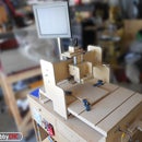
Step 21: Test - Apply Minimum Test Voltage and Verify 5VDC


To make sure no errors were made, apply at least 12VDC BUT less than 42VDC to TB6 labeled + and -.
Find an old 'wall wart' power supply (shown here) or a bench power supply and jury-rig it to the board for this test.
Exercise caution to ensure correct polarity to the board.
Verify that the proper testing voltage and polarity is present at TB6.
Yes, this is one of the "Free with any purchase" Harbor Freight volt meters. It is perfect for this project and the cost can't be beat. In this example, the meter is set to 20 in the DCV section.
With a voltmeter verify that +5.0VDC to 5.2VDC is present at the pad labeled +5VDC. The black test lead touches the “-“ on TB6. If not, review all the above steps and correct them. Failure to insure that +5.0VDC-+5.2VDC is present will BLOW the driver chips! (U5, R13, and R16 control the +5VDC voltage.) Go no further until +5VDC is achieved with this test.
Step 22: Install (2) MM74HC14N Hex Inverters

Install (2) MM74HC14N Hex Inverters (U8, U9). Orient the notch as shown in the PCB silkscreen. Trim the leads.
Step 23: Install (4) 23 Pin Driver Chips (and Optional Heat Sink)

Install (4) 23 pin Driver Chips (U1, U2, U3, U4) only after the voltage test (step 21, above) is successful. Driver ICs can only go in one way.
If you are planning to use a heat sink, it is recommended insert the driver chips into the PC board, then attach the heat sink to the driver ICs before you solder the driver IC. This will minimize any stresses on the leads (which might lead to a long-term failure). Use thermal paste between each driver IC and the heatsink. Note: the heatsink is an optional item (or build your own).
Trim the leads.
Clean the PCB with alcohol or a flux remover and inspect all solder connections with a MAGNIFYING glass to assure against any solder bridges. These will cause ALMOST ALL failures!


