

Introduction: Home Made Arduino Prototype Shield

Hi. I've just got myself an Arduino Uno R3 and I'm really new in the world of Arduinos. There's so much to learn and explore :)
One of the first shields that I'm tempted to buy is the Prototype Shield. I think building a prototype circuit right on top of the Arduino is pretty slick. So why buy it when you can make it? Trust me, it is very satisfying :)
The first thing that comes into mind is of course to make the PCB of the shield. The two most common ways of making your own PCB at home are the photo resist method and the toner transfer method. I've gone down the photo resist route because I find that the circuit produced is really sharp.
Let's start! :)
Step 1: Things That You Need


To make the Arduino Prototype Shield, you need these :
1. Hand drill to drill holes in the PCB for the components to go through.
2. UV PCB
3. A fluorescent lamp to expose the PCB.
4. Sodium hydroxide solution, acting as the photo resist etchant.
5. Ferric chloride, acting as the copper etchant.
Step 2: Preparing the PCB and Etching Photo Resist Layer


I found an EAGLE pcb file for the Prototype Shield from the arduino.cc website and modified it so that now it has more 5V pins and ground pins. Also added some text :)
Printed two of the circuits on a transparency and overlap them to get a perfect image.
Then I cut the PCB to size and used a small hand saw to cut it.
Peel off the photo resist protective sticker and lay down the transparency image on the photo resist coating.
Exposed the board under fluorescent light for about 8 minutes.
While waiting, I prepared the sodium hydroxide solution just by adding the crystals to water. Only put a small amount of it.
After 8 minutes just immerse the board into the solution and constantly agitate it. The unwanted photo resist layer should be washed off in around 10 minutes.
Next, is to etch the unwanted copper layers.
Step 3: Etching Copper Layer


Pour the ferric chloride acid into a plastic container. Make sure that you always use a plastic container because this stuff is corrosive.
Immerse the PCB into the solution and constantly agitate it. This will take around 15 to 20 minutes.
The trick of doing this is to agitate it for 30 seconds, leave it for 3 minutes, agitate it again, and keep on repeating this.
Finally, all of the unwanted copper layers are etched away and what's left is just the photo resist layer.
You can wipe them off with thinner or rubbing alcohol, in my case I used a rubbing alcohol swab.
The board with all of its copper glory! :)
Step 4: Soldering Connectors on the Shield


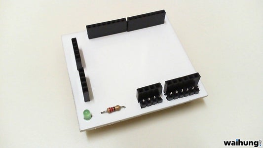


But before that, I painted the PCB white. Come on, that yellow is hideous.
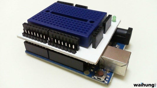
The final product is my home made Arduino Prototype Shield.
I've made a demo video on my home made Arduino Prototype Shield.
I hope you enjoyed reading this.
To read more on my Arduino discoveries or other electronics project, please go to my website at http://waihung.net
I've also documented the whole process on making this at my website :
Part 1 : http://waihung.net/?p=815
Part 2 : http://waihung.net/?p=849
Part 3 : http://waihung.net/?p=863
Thank you :)

Participated in the
Arduino Challenge


