

Introduction: Simple Arduino Wing Shield


I buy a lot of these stackable Arduino header sets because they are handy for a lot of things. I make some breakout boards with them, I use them to add some clearance between a taller shield and the next shield that I am stacking on top, and sometimes they are necessary when a shield doesn't come with headers or comes with only male headers. I recently found this set of stacking headers on Adafruit that includes the standard 6, 6, 8 and 8 pin headers as well as a 10 and a 3 pin header. Also, Sparkfun has recently started selling R3 stacking headers, which include a 10 pin header instead of one of the 6 pin headers like the old sets.
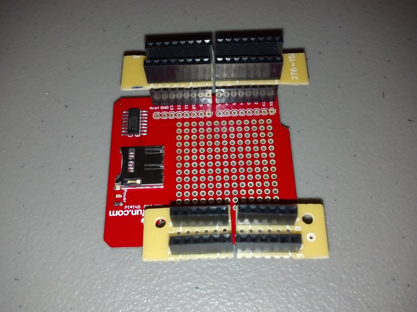
My most recent use for them was to create a "shield" like the Wingshield. I don't really want the screw terminals, so instead I wanted something that I could still use regular jumper wires for quick prototyping. I figured I could cut up some perf board and make something that would allow me to split the input and output headers.
Step 1: Parts
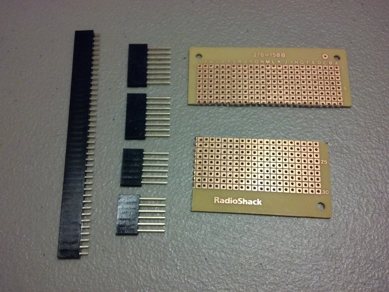
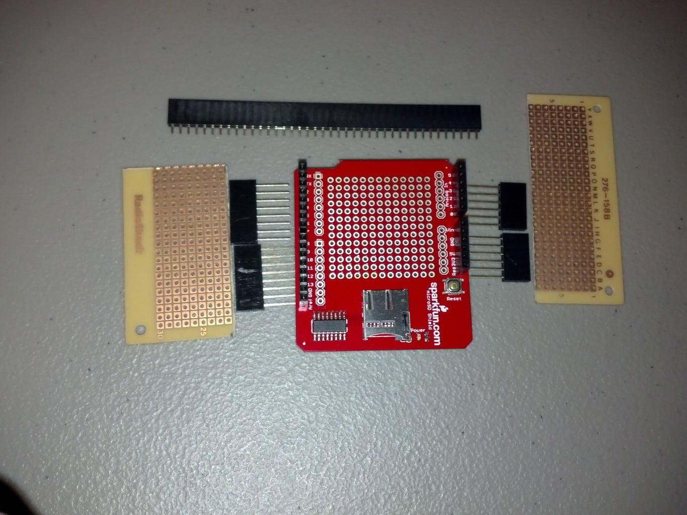
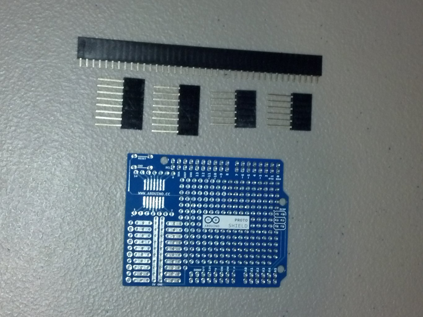

I had some perf board pieces leftover from another project. These pieces came from a 3" x 5" board that I got from Radio Shack. Unfortunately, all of the holes are drilled in different spots so things don't really line up correctly.
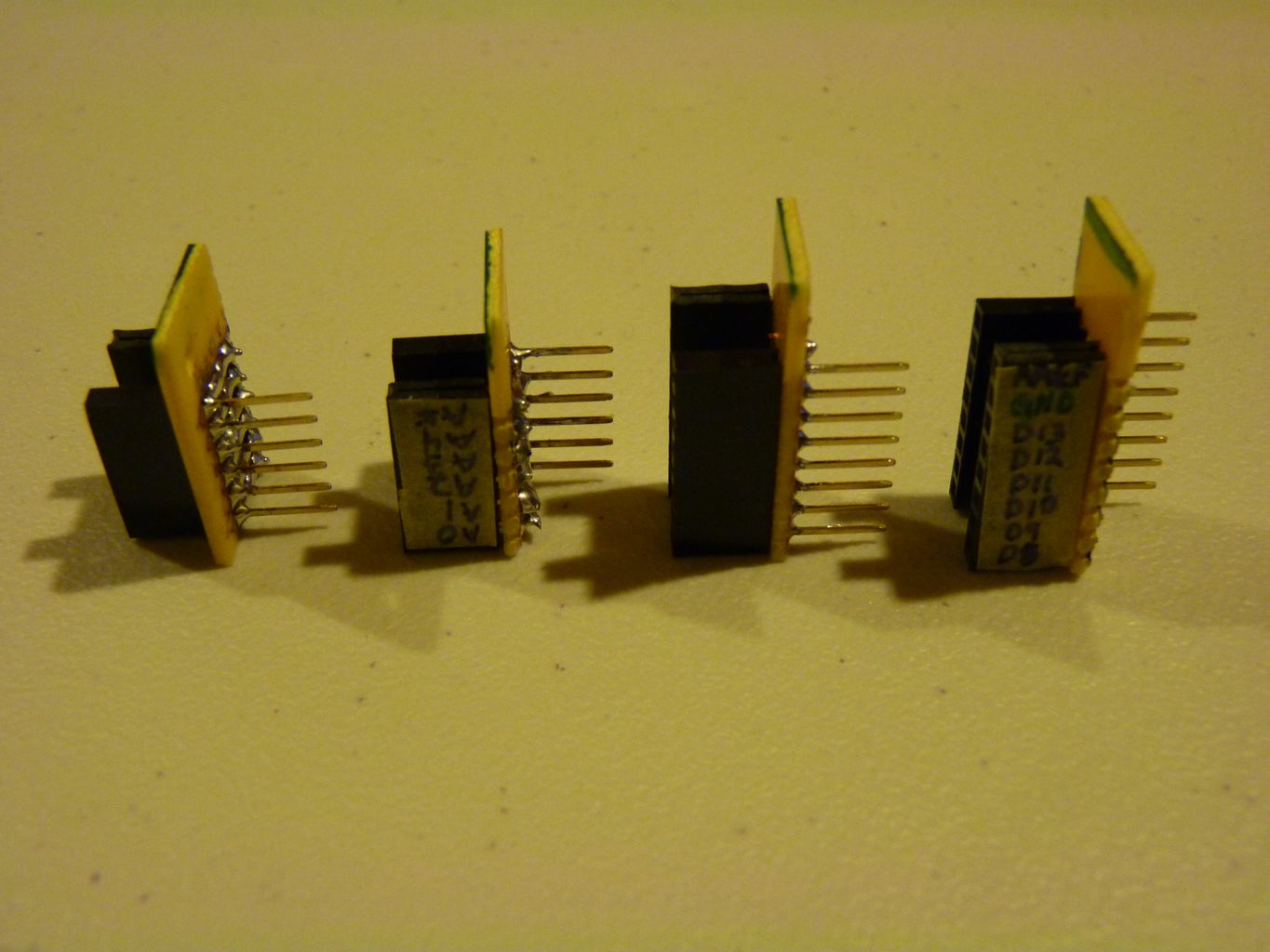
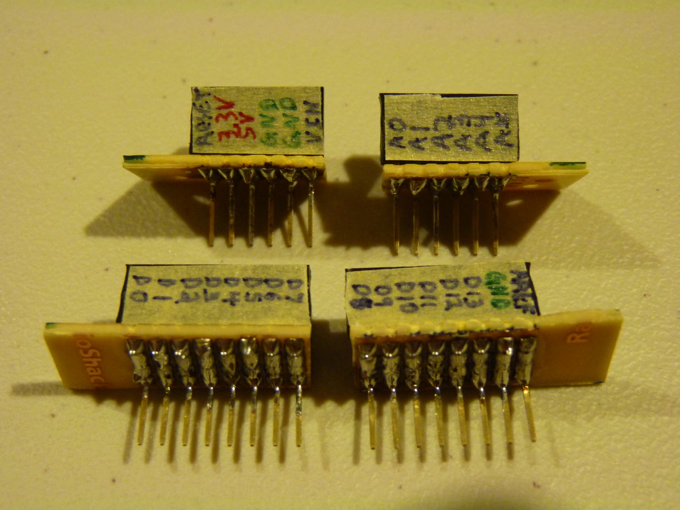
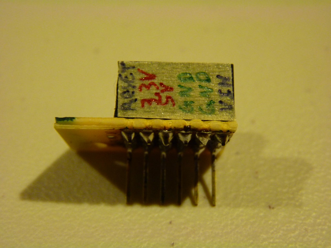
I trimmed 4 pieces of perf board that gave me a nice little handle on one side, but nothing on the opposite side so each header wouldn't interfere with the next one. I had to make them 4 separate pieces because the space between each bank of headers is less than the width of one pin on a standard perf board. I thought of taking a standard Arduino Protoshield and cutting the outer edges off with a Dremel, and while it would have been easier, it would have been a waste of a good Protoshield. This way, I was able to spread the additional female headers out 2 pins, where the protoshield would have had the new headers right next to the old ones.
Step 2: Cutting Headers


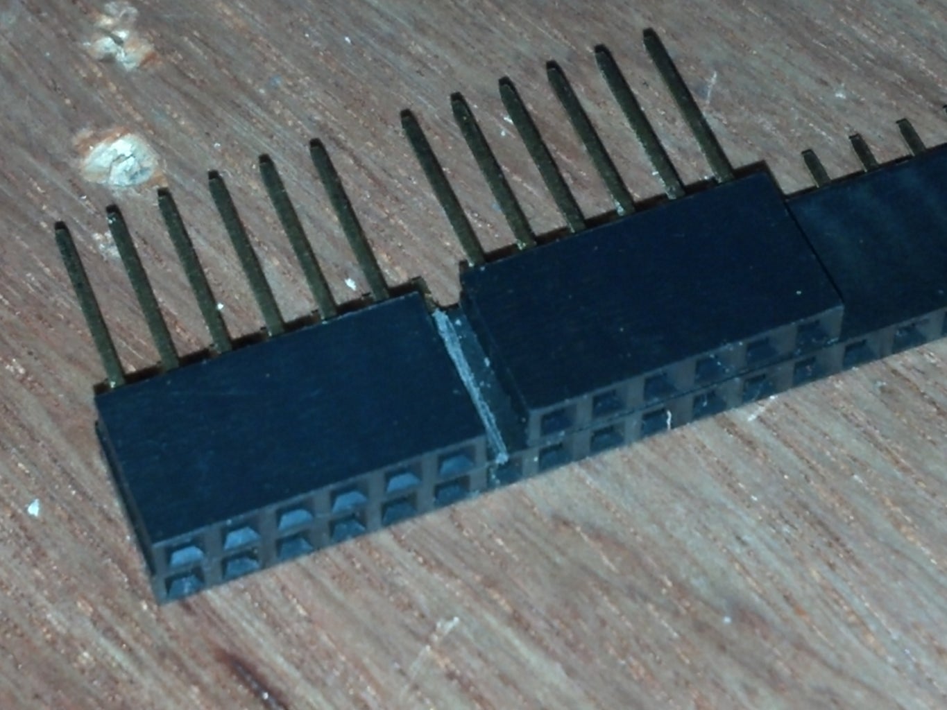

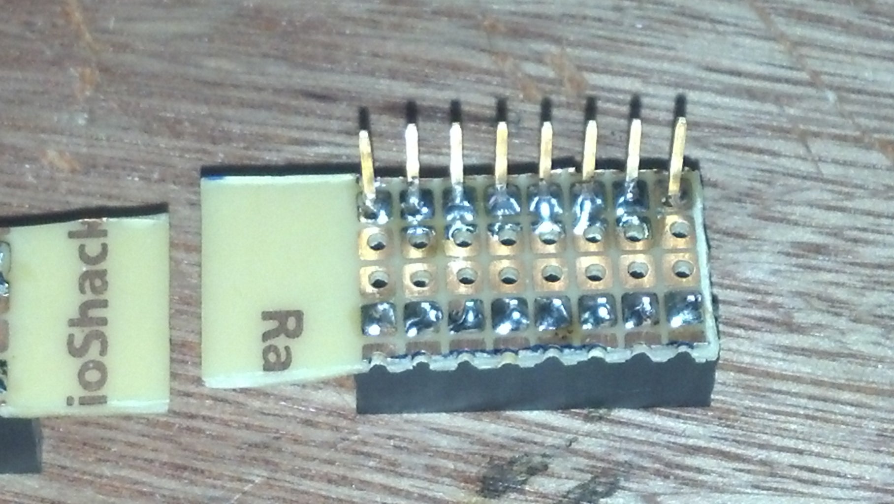
I buy these female headers in long strips that I score with an X-acto knife on both sides. If I need a 5 pin long header, I score the middle of the 6th hole on both sides and carefully snap along the score with a pair of pliers.
I already had the stacking header pins, so I just needed to make matching female headers. I snapped each piece in a row and cleaned up the ends by shaving it down more with the X-acto knife.
Step 3: Lining Up the Pins
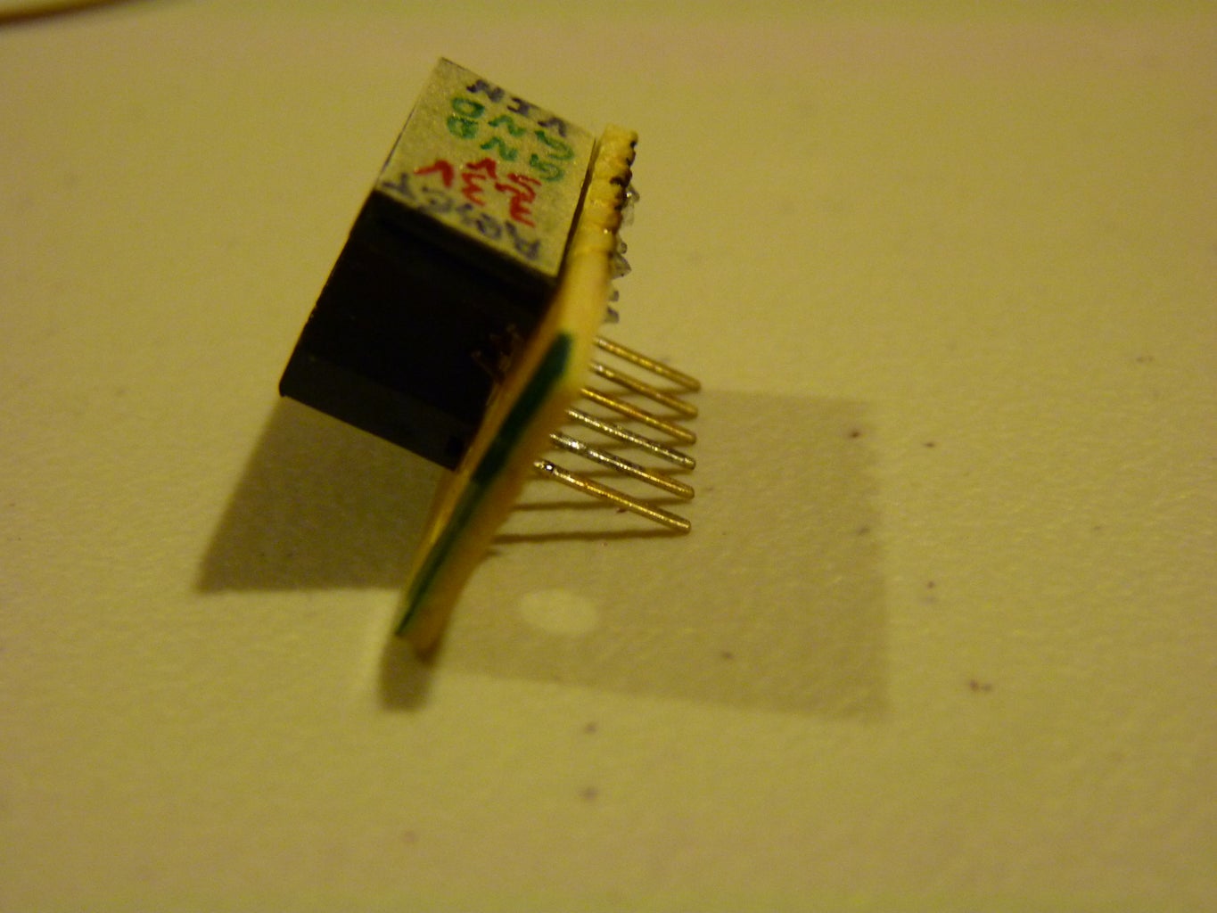
I like to do line up header pins by putting a little tack solder on one of the end pins. I push the header into another board so it is square to the board, then I put a tiny bit of solder on the last pin to hold everything in place. If I can't put the pins into another board, I will usually just balance the board on the pins, and move the pins so they are square while the solder is still liquid. It's easy to straighten them again and again if you only have solder on one pin.
I soldered both headers in place with this method and made sure they were parallel and square.
Step 4: Soldering


I did this part a little ugly, but it works. Sometimes, you just have to make things ugly.
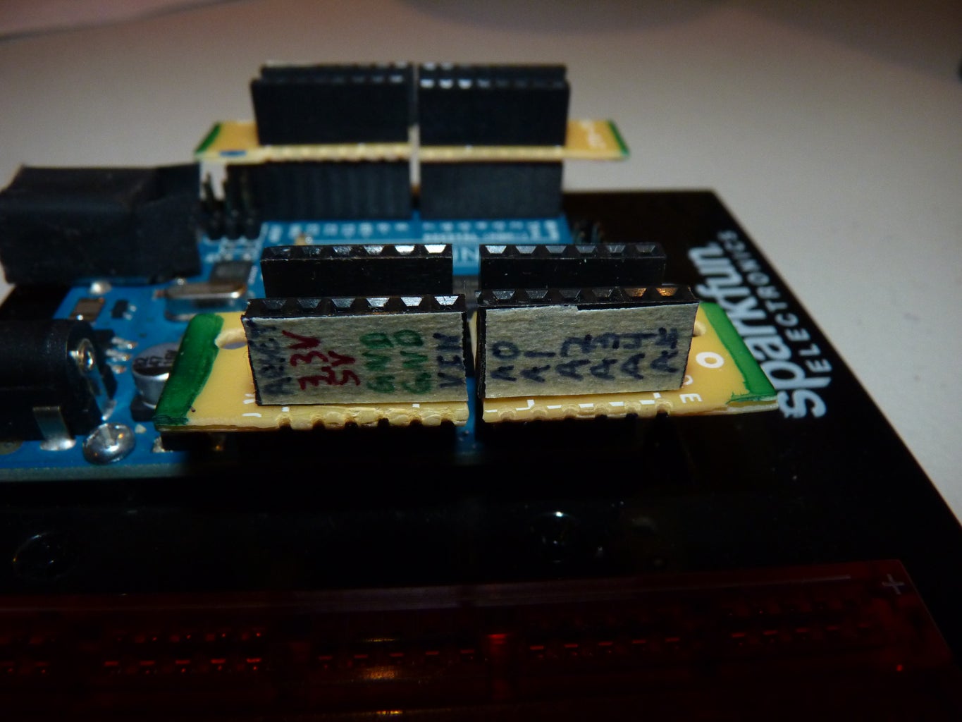
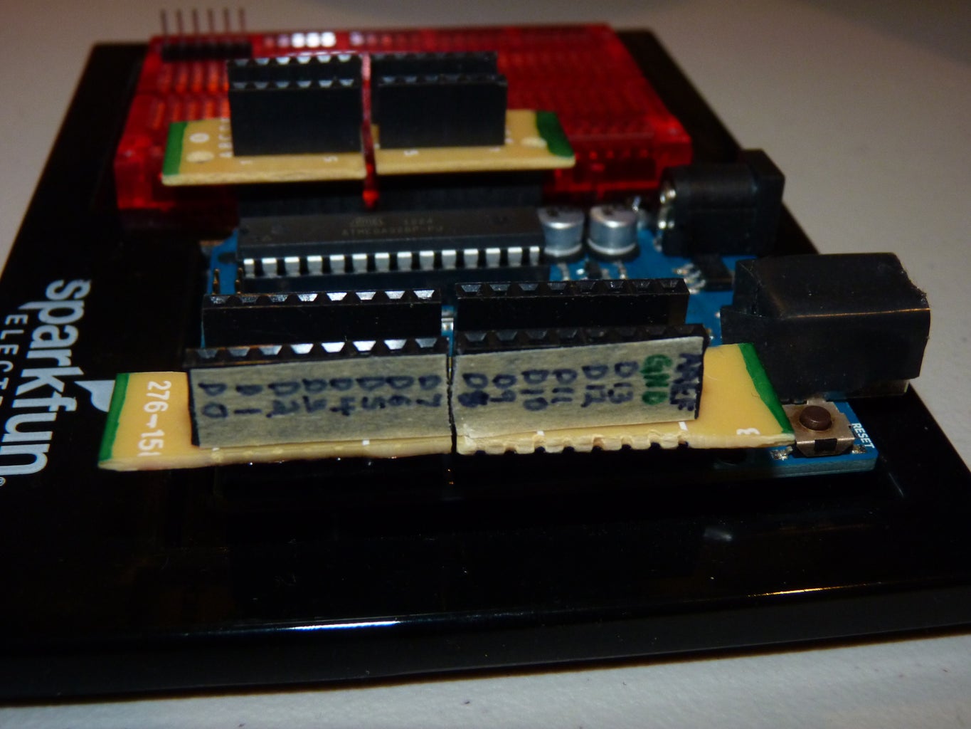
I use UTP wires from old CAT5 cables for hookup wires for breadboarding. I stripped the insulation off a long piece of one UTP wire and made a bunch of little U's by wrapping it around the end of my needle-nose pliers. I then clipped each U off the wire and dropped it into the 2 holes between the female headers and the stackable headers.
I soldered each U in place, then put an excessive amount of solder to bridge the gap to the headers on either side. I used my multimeter's continuity setting to make sure I had no connection to the neighboring pins but that I did have the related headers connected.
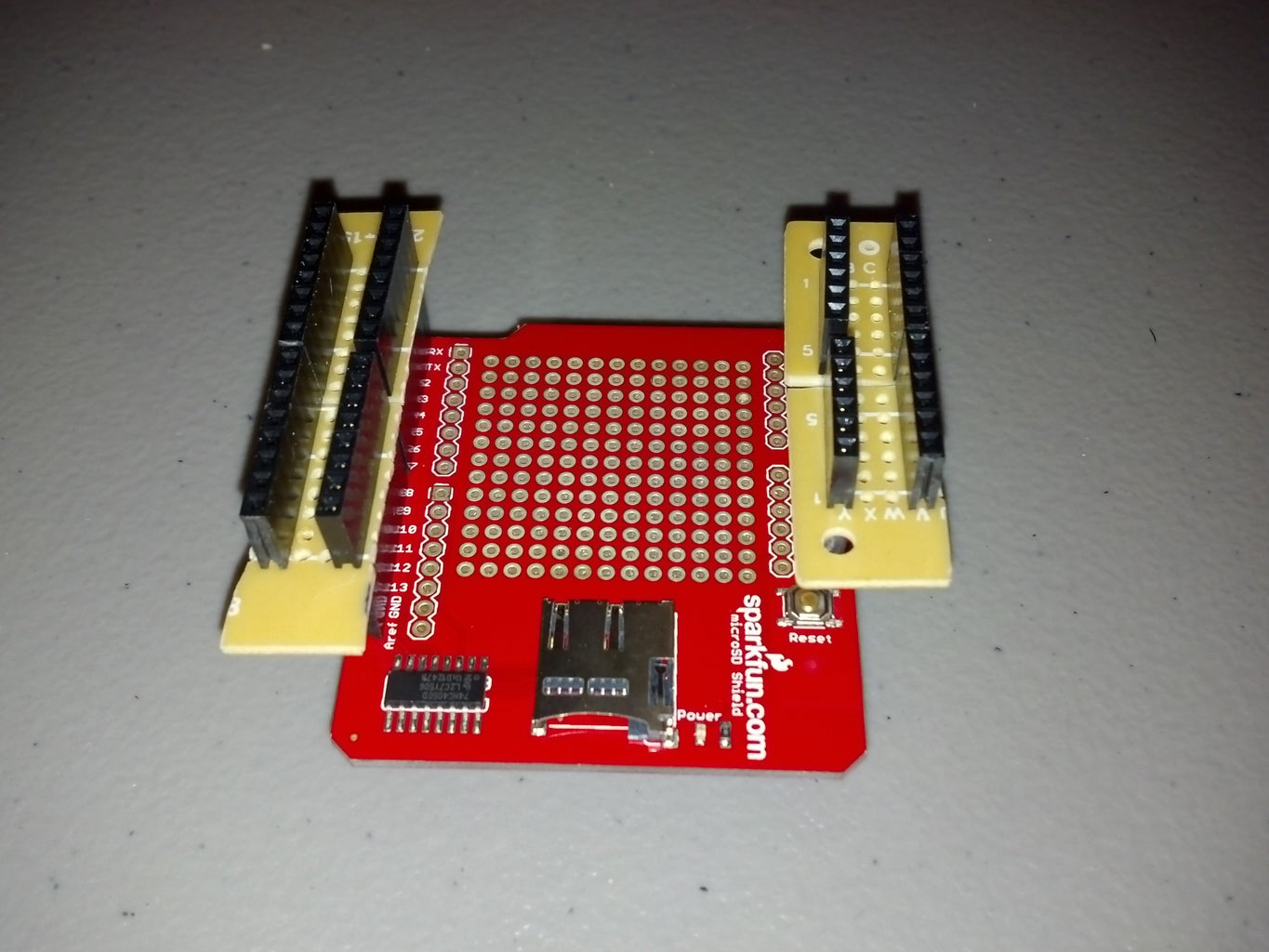
Step 5: Finish


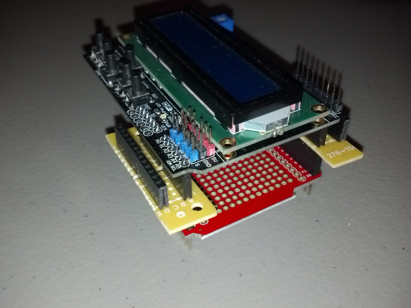
The finished product is exactly what I wanted it to be. I can now make connections to all of the pins even with a "top shield", like an LCD screen, that doesn't have female headers.
Overall, I like the way these came out but there are a few things I would do differently:
- Use R3 headers instead of the standard ones.
- Use 90 degree female headers instead of the standard ones.
- Use bigger pieces of perf board and wires to eliminate the blobs of solder.

Participated in the
Supercharged Contest

Participated in the
Manly Crafts Contest

Participated in the
Hardware Hacking


