

Introduction: Home Automation System Using Arduino and SIM900 GSM Module


Hi there! As I've almost finished my studies at Faculty of Engineering, I had to make a graduation project and my thought was to make a jaw-dropping thing (I know that's hilarious :D ) to show everybody that I'm a good prototype maker and I can turn ideas into real and useful things.
I know GSM controlled home automation systems are widely used and can be found easily on internet, but as we all know, the prices are very prohibitive for general consumers. This is why I've tried to build some sort of device based on open-source knowledge that can be replicate by all the hobbyists, even if they are amateurs or professionals.
So I begun to think what kind of basic home appliances could be remote controlled via GSM network and nothing else? We all know, that you can control lights, heating, multimedia system and so on, but I've tried to make my project closer for my basic needs: lighting and heating (optional - garage doors, but it's not my case because I live on a 3rd floor apartment).
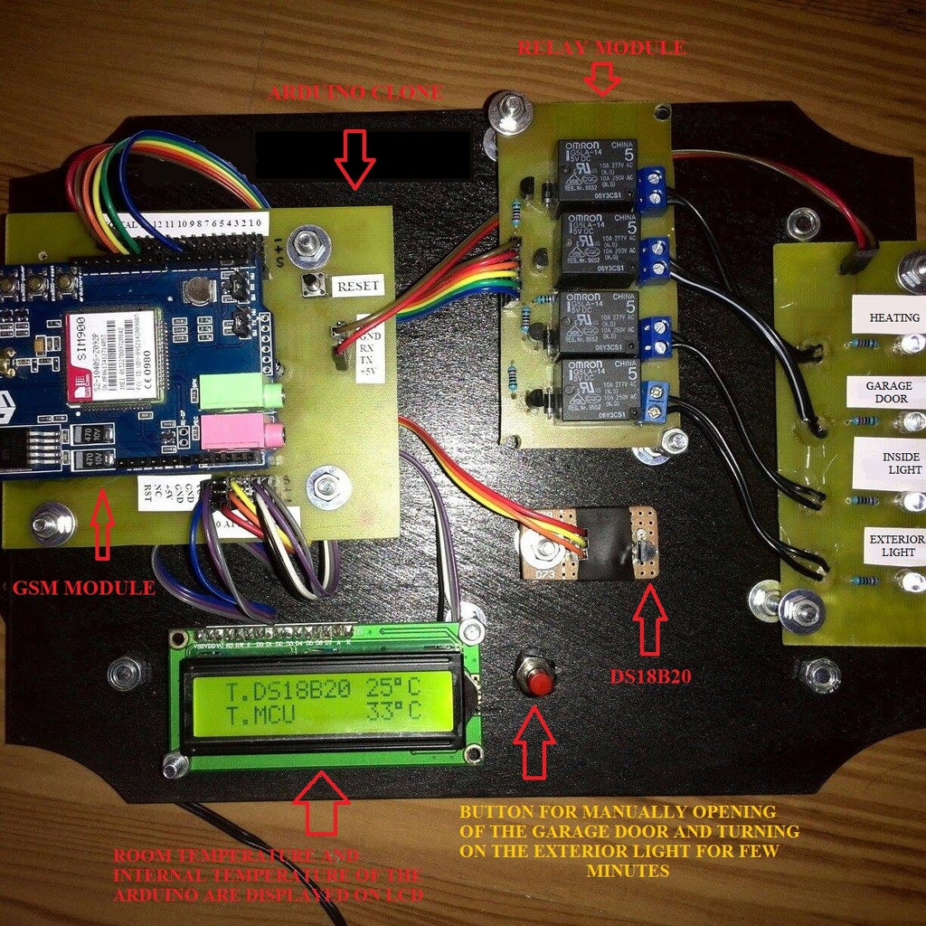
I mention that the finished prototype, seen in the photo, can be used safely (with a bit of tweaks, of course) on any kind of building with or without garage (the garage door relay can be repurposed for any other activity)
For this project I've used:
1. An Arduino clone
2. SIM900 GSM SHIELD
3. Relay module
4. 2x16 LCD Display
5. DS18B20 temperature sensor
6. Push button
7. Some Dupont wires
8. A led module (this is optional, if you have a chinese relay module with built in LEDs)
9. Some nuts and bolts to mount everything in place
10. A wooden chopping board or other kind of wooden board for propper display of the components
The costs?... The gsm shield was about 40$ from eBay, LCD...2$, DS18B20...1.5$, Dupont wires another 2 bucks, push button...few cents, the relay module 2-3$ to make and the Arduino clone was less than 10bucks to make...
Conclusion: you can build your own basic GSM home automation with less than 100$!
If you like this instructable please feel free to vote it on each contest it is subscribed! Thanks! :)
Step 1: Making the Arduino Clone
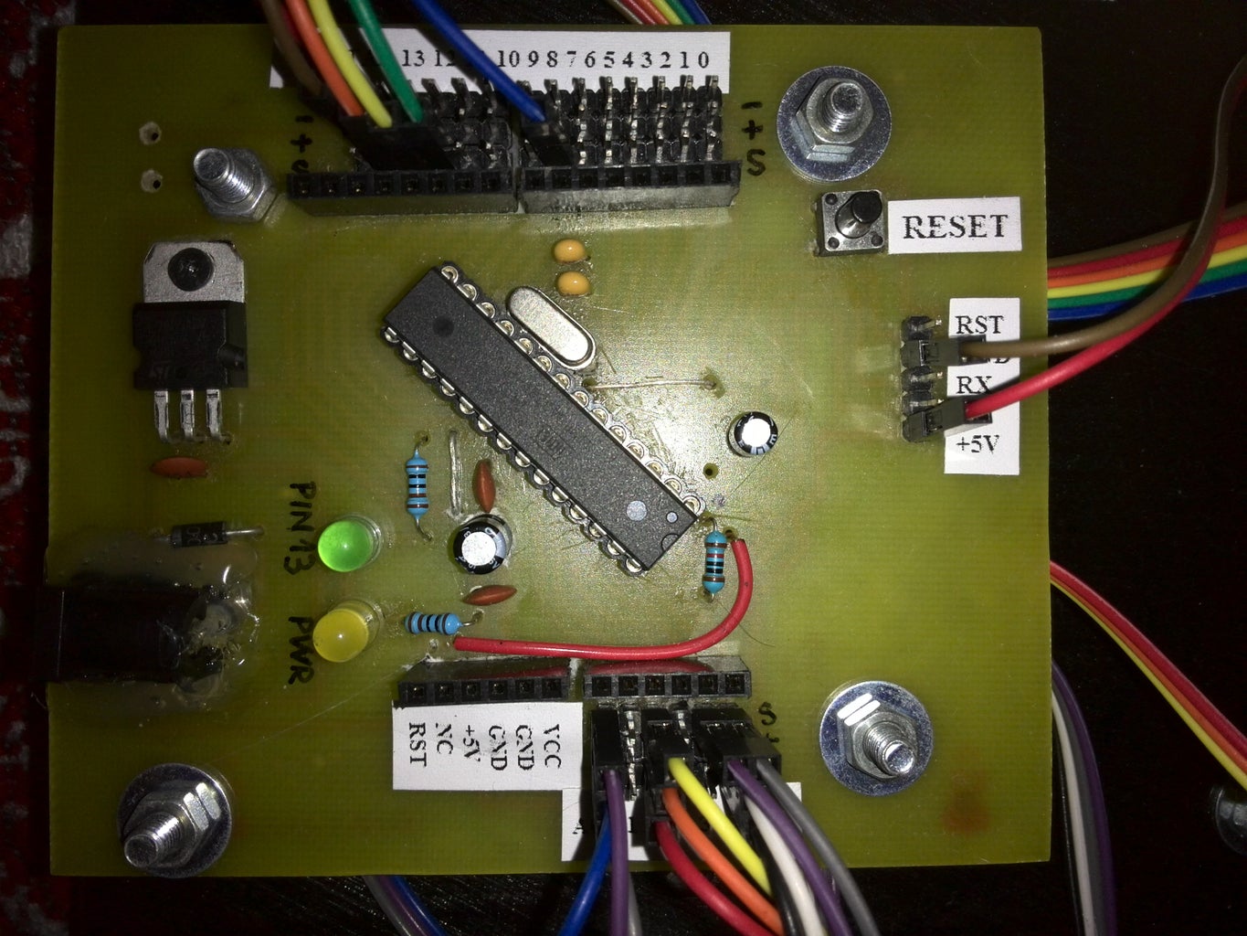

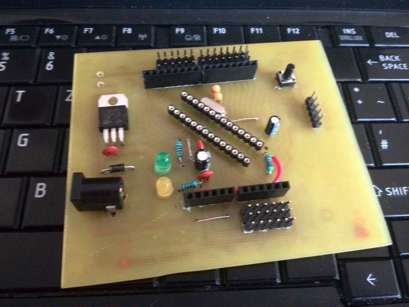
For this project I wanted to make a stand-alone Arduino board because I only have one Arduino UNO and I'm using it for my random project, so the need for a clone board was huge. I've managed to modify a schematic provided by my good friend Nicu Florica, which is derived from Nanino project and for my application I've added few pins to facilitate the connection of other devices (sensors, relays, etc) when a shield is attached on the main mother connectors.
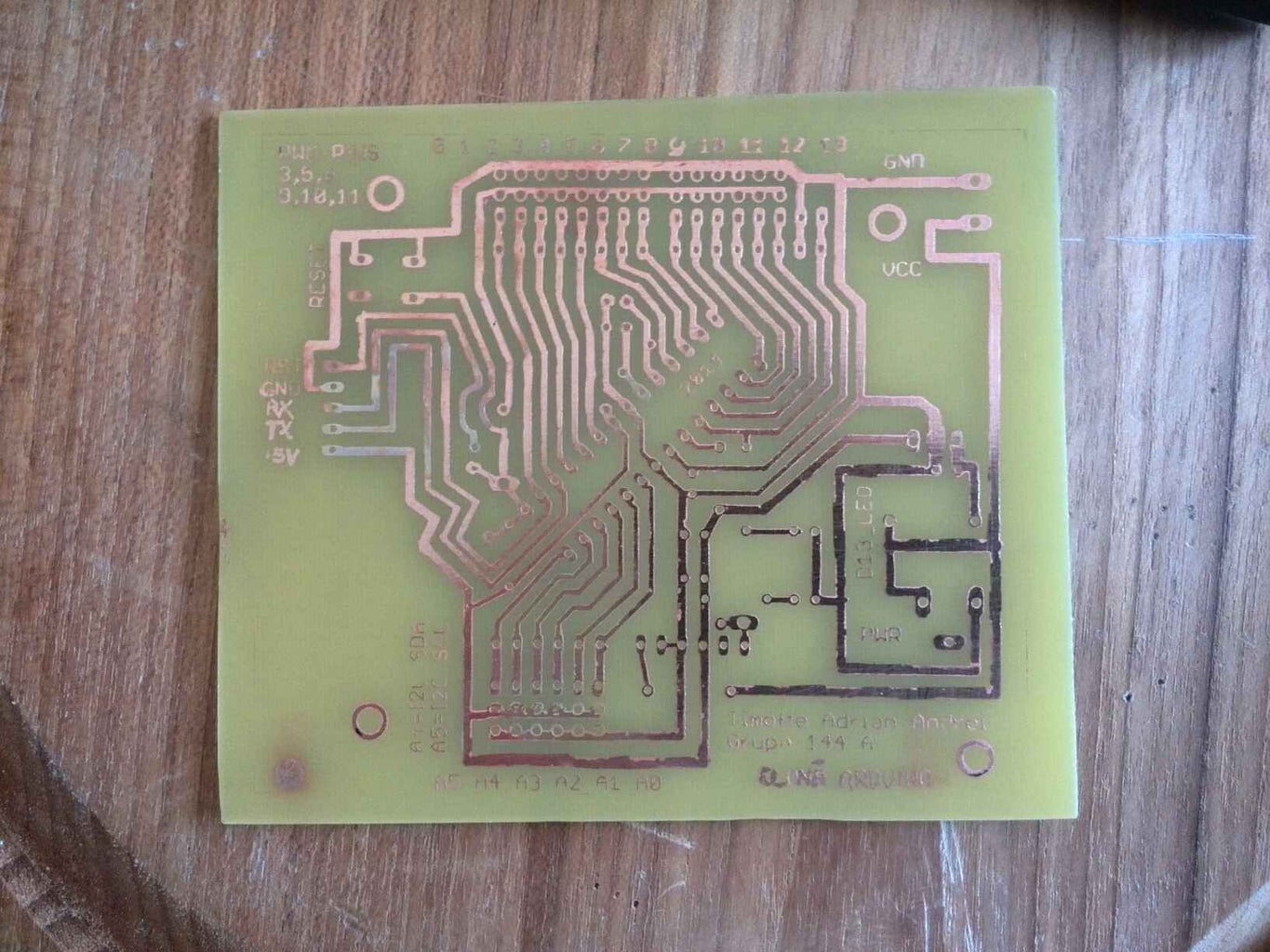
The method used to make the PCB is just p'n'p using Oracal 641 paper, an 8 years old HP LaserJet 1018 printer, a clothes iron, ferric chloride etchant, some kind of dissolvent to clean out the toner traces after etching process and obviously a copper-covered board ready to be turned into a PCB.
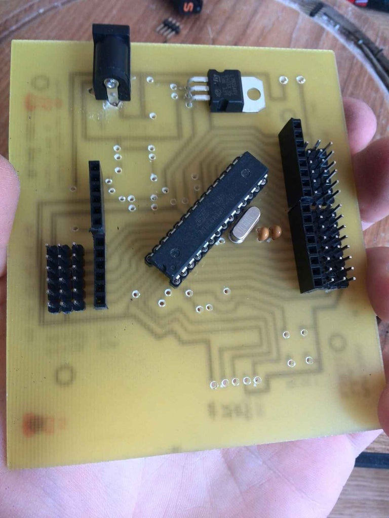
After etching and cleaning the finished PCB, I've drilled all the holes for components and connectors, I've soldered them all, I've checked for short circuits and the result can be seen on the last photo.
The BOM is:
- ATmega328P-PU
- 16MHz Quarz
- 2 x 22pF caps
- 3 x 100uF caps
- 1 x 10uF cap
- 1 x 47uF cap
- 2 x 10k resistors
- 1 x 1k resistor
- 1 x 1N4007 diode
- 2 x 5mm LEDs
- 1 x 7805
- 1 x barrel power connector
- 1 x push button
- some male and female pin headers
Because I don't think that the etching and soldering processes are important, I've only made few pictures of the critical parts of the building.
Attachments

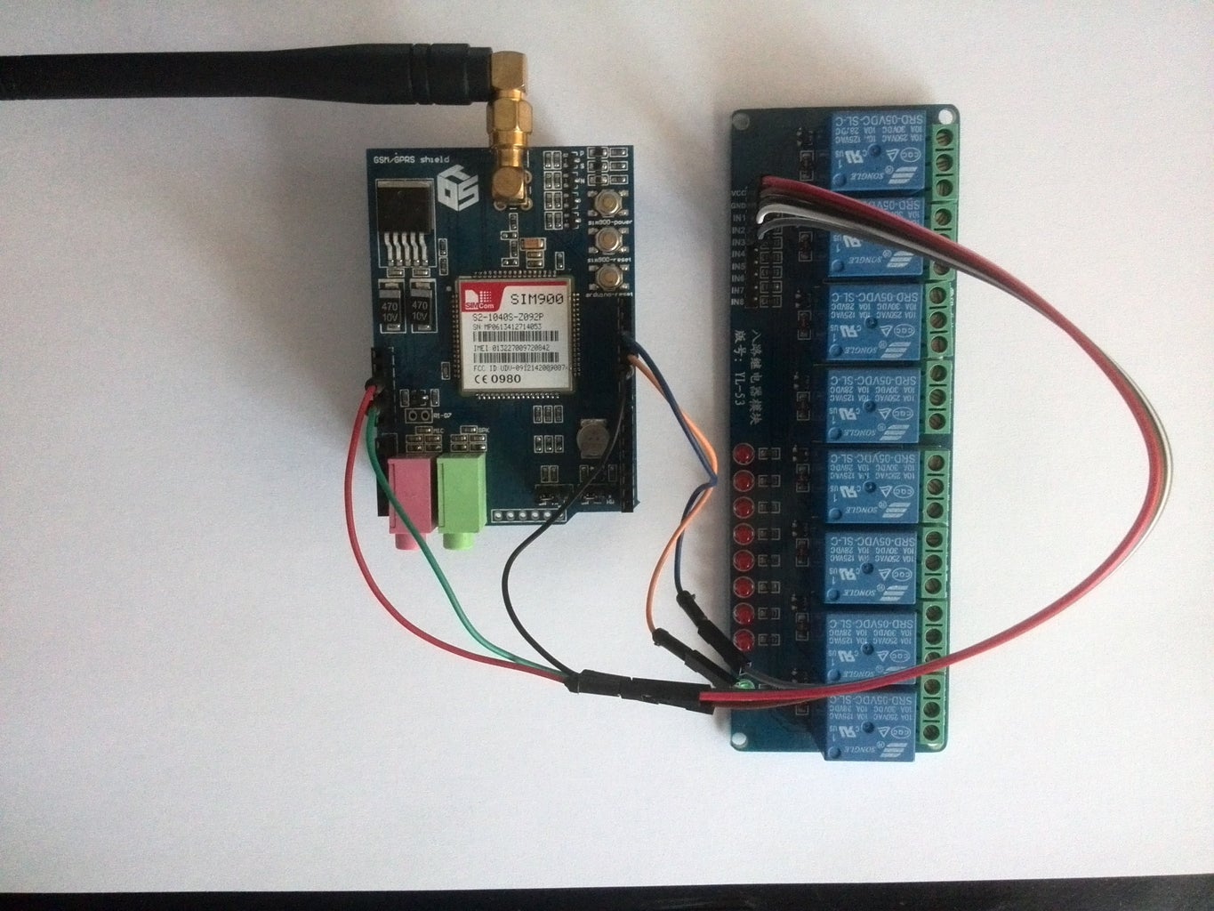
Step 2: Making the Relay Board

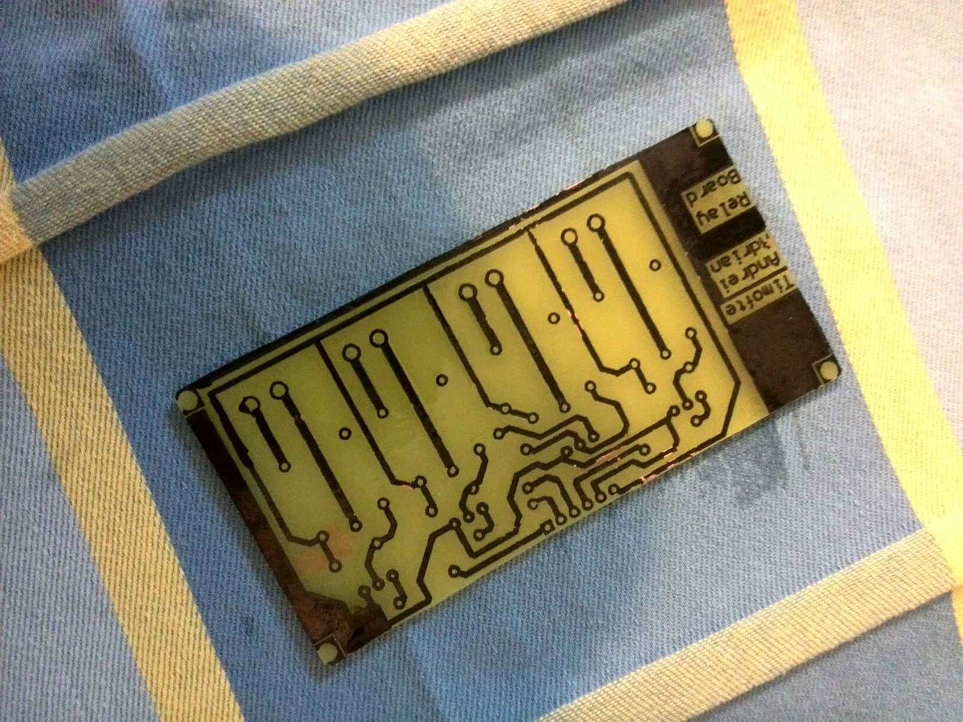


Another friend of mine (Vlad) made a PCB schematic for the relay module because I have been busy with some exams and programming. He's actually a master in Altium Designer so he made the schematic in no time. As you can see, the relays are 5V ones, each one controlled by its own BC639 NPN transistor and also equipped with its own anti-parallel diode to prevent the destruction of transistors.
The BOM of this module is:
- 4 x Omron G5LA-14
- 4 x BC639 NPN transistors
- 4 x 1N4002
- 4 x 1k resistors
- 4 x screw connector
- 1 x 6pins male header
Step 3: GSM Shield
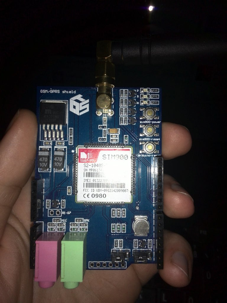
That's not much to say about this shield... I purchased it from ebay for about 35$ and it works just fine. The sad part of using it is you cannot add interrupt features to the project because it uses pin D2 and D3 for software serial communication and those pins are also used by internal interrupts system of the microcontroller. Also pins D7, D8 and D9 of the Arduino are reserved for incoming call presence, software power up and software reset of the GSM shield.
Step 4: Testing the Schematic
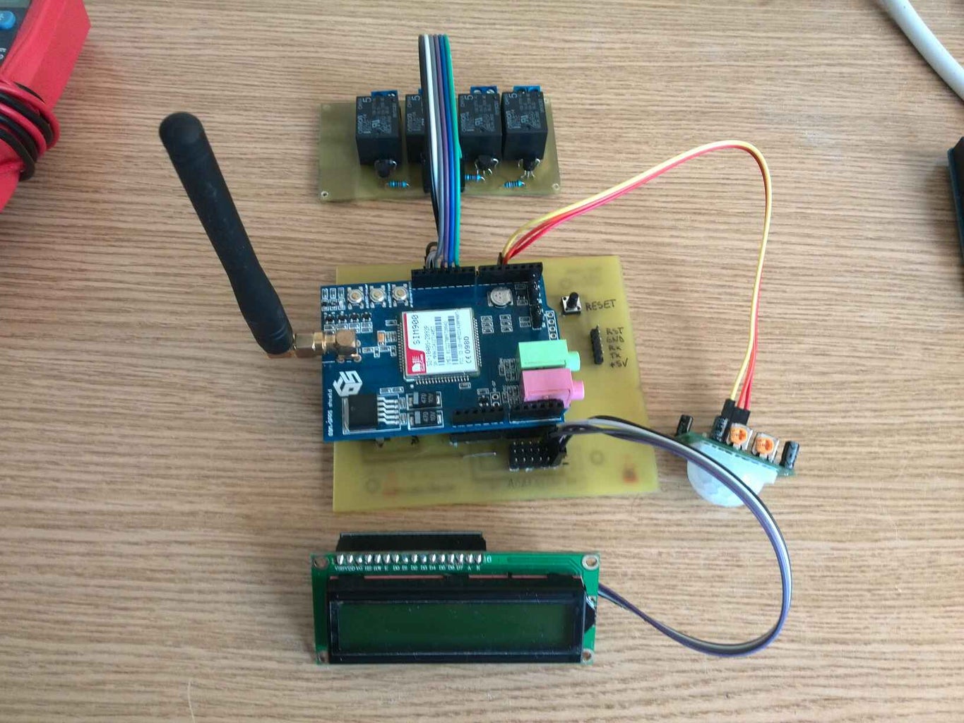
After putting almost everything together, I've made a test using each of the component to see if it works well or not, but I realized that the PIR sensor sucks. My second idea was to implement some security features in the code, but I've seen that PIR sensors turns high randomly even if the potentiometer from the top of it are turned or not. That's shame...
Step 5: Making Some Sort of Breakout Board for DS18B20


In the pictures you can see that the DS18B20 sensor is powered in parasitic mode, but after a lot of testings with bad results (-127degree C error), I've switched to direct powering and everything was just fine.
Step 6: Putting Everything Together...
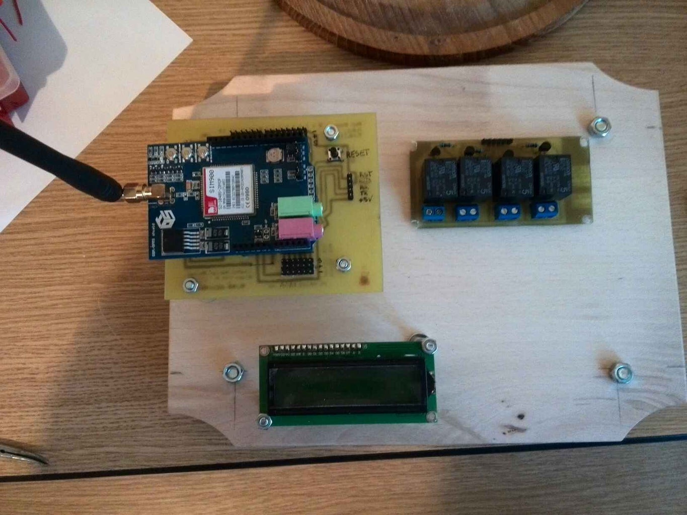
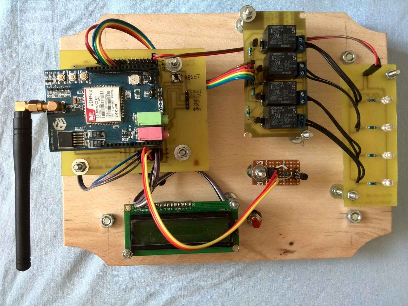

For the base, I used a wooden chopping board that I've drilled some holes on it to fix all the components in place with bolts. Also for the finishing touch I've used some black spray paint to make the board a little bit sexy. :D
So if you ask for connections between Arduino clone and other components this is the order:
1. LCD Display is connected through i2c using arduino's A4 (SDA) and A5 (SCL)
2. Relay module is connected on digital pins 6, 10, 11 and 12. Note that I've didn't used digital pins 7, 8 and 9 because are used by the GSM shield
3. DS18B20 is connected to the A0 pin
4. The button is connected to A2 pin
Step 7: Sending Text Messages and Receiving Feedback

This is an example with sms commands and the feedback received from the system... Sadly I only did that in romanian language, but you get the picture of the whole thing. :)
Step 8: And a Short Demo...
I've made a short demo with this system, but because of lack of time I only made this in my native language, romanian. You don't need to understand what I'm saying, just watch carefully and don't forget to vote if you like this Instructables! Thanks alot guys and if you want some advices or you have some advices I'll be happy to read your comments.
Step 9: PLEASE READ THIS!!!!
Please do not send any requests for the code on the comment section or on private messages. As I said before, the code will be soon available to be purchased for few $ via PayPal because I really need money to finance my future projects. Please understand that it took me a week or two of hard labor just to put everthing together you've seen in this project and I cannot take back that spent time. Thanks!

Participated in the
Remote Control Contest

Participated in the
Epilog Challenge VI

Participated in the
Home Technology Contest


