Introduction: Home Built CNC Machine Part 1 - Supported Linear Rails
This instructable is part of an on-going project to build a home CNC machine. In this part of the project, I will show you how to build a supported linear rail which can be adapted for the desired length (X-Axis) of your own CNC project.
Most people are put off from building a useful sized CNC machine because of the cost of parts. Others use angle iron and skate board bearings for their linear rails. The instructable may look compllicated but it really is not. With a little care, it is possible to make an accurate CNC machine and will enable you to build a decent sized machine.
Step 1:
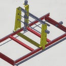
When I first designed my machine, I started to look at much cheaper alternatives to aluminium box sections, proprietary lead screws and proprietary linear rails. I finally decided to build my machine to this design which includes some junk yard parts and home made linear rails which can be made to any practical length required. The parts shown in yellow are steel parts which are fabricated by a local laser or plasma cutting shop and will form part of a later instructable.
The two end sections of the base were cut from industrial shelving brackets obtained from my local junk yard to which I have welded cleats for connection of the linear rails. The two (red) intermediate rails are steel channel with steel cleats welded on the end. The overall size of my machine bed is 800mm x 1800mm but of course you may build your machine to whatever (practical) size that you wish.
Step 2:
The linear rails - Construction.
The following tools and parts will be required for this part of the project:
• 2 x 16mm, bright steel rod cut to required length or other smooth finished 16mm steel bar that can be bored and threaded with a hand tap.
• 12.5mm x 8mm electrical stand-off spacers. (sufficient to provide support at 150mm intervals along whole length of rail.
• 2 x 25mm x 5mm, bright steel bar to same length as steel rod.
• 2 x Aluminium 'I' section support rails. I used dividing strips from demountable office partitions that I got from my local junk yard. If this is not available, there are many different lengths of cheap, 'I' sectioned spirit levels up to 1800mm (or more) length and with milled edges available on eBay.
• A bench or pillar drill.
• 4.2mm, 5mm and 10mm (for countersinking) drill bits
• 5mm tap.
• A quantity of M5 x 10mm, countersunk, socket (allen) ended bolts to suit length of rails.
• A quantity of M5 x 25mm, countersunk, socket (allen) ended bolts to suit length of rails.
• A made-up drilling jig.
• A set of hex (Allen) keys - preferably ball-ended.
• If you have access to a small lathe, you will find it useful for turning small pins for your drilling jig.
Step 3:
The first thing that you MUST do is to take the 16mm rod to a local engineering shop and have a 1mm deep flat ground on one side for the whole length of each rod. I have ruined several pieces of rod trying to drill accurately but it is impossible to centre the drill bit on a curved surface. Even an end mill bit is not sufficiently stiff to keep the holes centred.
Step 4:
Although it may be possible to do the next operation without a jig, making one is well worth the time and effort to ensure accurate drilling.
This is the jig I made up from a 5mm piece of steel with two strips made up 3 pieces each of 5mm steel bolted together to make the strips 15mm high. On the drill table beside the jig is a positioning tool made up with two 5mm rods on the outside with an old 4.2mm drill in the centre. The jig is positioned on the drill table first by using a 10mm drill into the centre hole. The four holes to the left of the jig strips are drilled so that the positioning jig can be set at an initial 75mm in from the end of the rod and then at 150mm for each successive hole.
To use the jig, the 16mm rod is inserted between the strips with the 'flat' facing upwards and butted against the positioning jig which is at the 75mm position initially. The 25mm bar is centred on the top of the strips and held in the centre by using additional strips either side of the bar and secured by cramps. I used small brass dowels (turned on my lathe) instead which were fitted into additional holes in the jig strips.
Both the bar and the rod are then drilled using the 4.2mm drill. The depth stop on the bench drill must be set so that the last 3mm of the rod are not drilled. The positioning jig is then reset to provide 150mm spacing for the holes down the remainder of the rod. I seriously recommend that the jig is cleared of metal swarf each time the work pieces are moved up the jig to prevent scratching of the 16mm rod. You will find it necessary to use supports for the ends of the rod and bar if they are longer than about 750mm as it will be difficult to keep the work pieces flat in the jig otherwise.
Once all of the 4.2mm holes are drilled down the length of the rail, remove the 16mm rod then redrill each of the holes in the bar using the 5mm drill then countersink each hole using the 10mm drill.
I recommend that when drilling the 4.2mm holes, that the first hole in the rod is tapped and the first hole in the bar drilled out to 5mm and countersunk, then the rod and bar temporarily fixed together using one of the M5 x 10 bolts before drilling the remainder of the 4.2mm holes. This is to ensure that the holes remain properly aligned throughout the length. After drilling is completed, tap each hole in the bar using a first, second and plug tap for each one.
If you have access to a foundry, you may be able to have the rods induction hardened for additional life.
If you can get the jig parts laser or plasma cut, I can supply a .dxf file to submit to the cutting shop. The dxf file is slightly different to the one that I have used as I have included a large cut out at the drilling point in order that swarf does not jam down the side of the rod and can be cleared easily using an old paint brush during the drilling phase.
Step 5:
The next operation is to drill the fixing holes from the flat bar into the 'I' section.
First clamp the flat bar onto the 'I' section making sure that they are properly aligned throughout it's length and with the previously drilled countersunk holes facing towards the 'I' section.
Using the 4.2mm drill, drill through both the flat bar and the flange on the 'I' section 6mm from the edge of the bar and on alternate sides between the previously drilled holes. Then separately drill out the holes on the flat bar to 5mm and countersink with the 10mm drill.
Once again, I would recommend that the first hole in the 'I' section is tapped and the first hole on the bar is enlarged and countersunk then the two pieces fixed together before drilling the remainder of the holes. You will need to check the alignment regularly as there is often a curvature in the flat bar or I section. As long as they are perfectly in line with each other, they can be made straight by using shims on the cross-members
It is not necessary to be particularly accurate with the spacing between these holes along the length of the bar but they must be on an inscribed line at 6mm from the edge else you will find it extremely difficult to insert and tighten the M5 x 10mm bolts under the rail if they are much further than 6mm from the edge. You will also find out why I recommend a ball-ended hex wrench for this job.
Step 6:
The next operation is assembly of the rails. First assemble the 16mm rail to the flat bar using M5 x 25 bolts with the electrical stand-off spacers between them. The spacers have an internal diameter of 4.3mm when you buy them and will need to be reamed out to 5mm using a suitable holder in your bench drill. I found it particularly easy as I was able to use my lathe to centre drill the spacers with a 5mm drill.
Step 7:
The final operation is to fix the rod and bar assembly onto the 'I' section (Fig 7) using the M5 x 10mm bolts. There is very little clearance to insert the bolts under the 16mm bar and you will almost certainly require to use a ball-ended hex (allen) key to tighten the bolts.
I hope you found this instructable useful. If you did, please vote for me as I have entered the ShopBot Challenge.
The next part of this instructable will be to assemble and fit the gantry and 'Y' Axis to the linear rails. I will be including DXF and DWG files in order to get the parts laser or plasma cut.

Participated in the
ShopBot Challenge


