

Introduction: Read/emulate Remotes With Arduino and Raspberry Pi


Remotes are everywhere. They are the interface to your TVs, music systems and what-not. You probably have a few spare ones lying around, devastated at the demise of their better halves. Cheer them up and put them back into use! (Skynet approves...)
Here are some reasons why you should implement or emulate remotes in your projects (there is really no need to write down any reasons, but the things is, I really like lists):
- if you need to hide your project someplace and need to operate it covertly like spy devices.
- if project will be installed in some inaccessible or high reaching place like DIY overhead projector, bird house water supply, etc...
- if you need to remove all those ugly buttons on your project enclosure.
- if you want to control your remote-controlled devices like TV with an Arduino or Raspberry Pi.
- if you want to survive the singularity (earn brownie points with Skynet while you still have a chance)
- because remotes are cool
In this instructable, I'll show you how to: (Warning: Another list follows)
- Using Arduino:
- read remote signals using interrupts, so you can do other stuff on your Arduino while waiting for someone to press that button. Also interrupts will get the most accurate timing data.
- decode remote codes to identify individual buttons without overflowing your memory. Usually saving a few button's IR codes will fill up your Arduino's memory...
- recreate IR signals for any of your remote's button super easily. Control your TV with an Arduino!
- Using Raspberry Pi:
- read IR signals and implement it in your Python scripts. Play games with remotes!
- recreate IR signal using Raspberry Pi. Make a universal remote control.
Note: Since posting this instructable, I've discovered Shirriff's IR library for Arduino and I suggest that for the Arduino part of this instructable as it's extremely easy to use. But if you want to understand how IR really works on those remotes, the instructable will provide a good read. Maybe if I get some free time, I'll add steps for Shirriff's IR library: https://github.com/shirriff/Arduino-IRremote
Step 1: Go Get Stuff
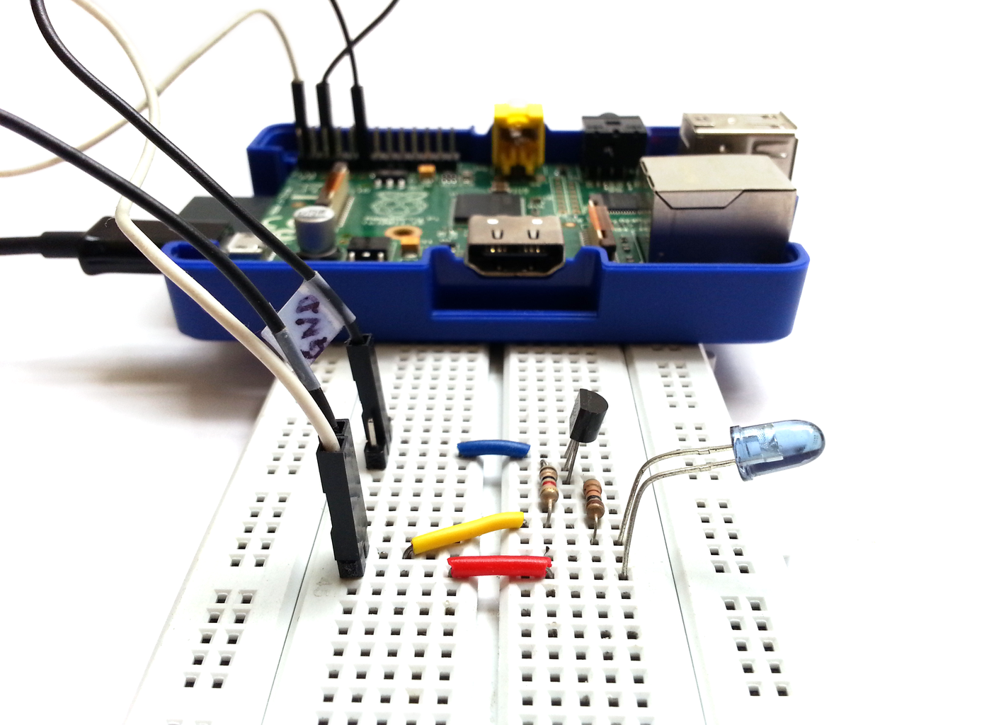
What you need depends on what all you want to do. Still the list is quite short:
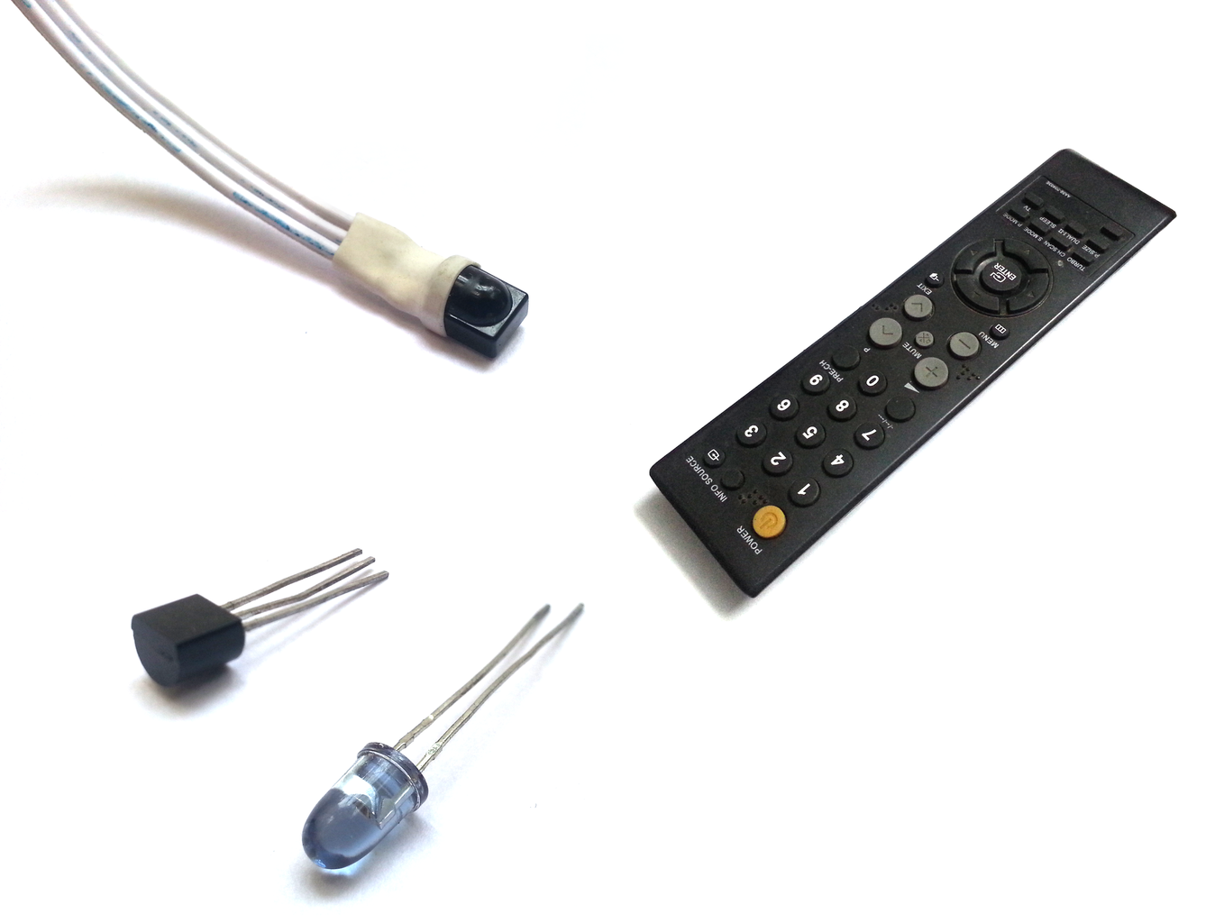
- IR sensor (adafruit link)
- IR LED (adafruit link)
- Arduino or Raspberry Pi
- NPN Transistor PN2222
- 1K ohm resistors
- 220 ohm resistor
- Some connecting wires
- Of course, a remote control
Step 2: IR Basics

There are already very detailed instructions on how to read and recreate IR codes from a remote. I'll try to build upon ladyada's IR tutorial. I'll explain the basics and give a brief overview, but I'll keep linking to ladyada's tutorial's pages for detailed instructions.
IR stands for Infra-Red. This is a part of the spectrum that goes beyond the red color and invisible to us. IR can be better called as heat waves. Whenever something radiates heat, be it a bulb, fire or sun, it radiates infrared rays. Even something that is not glowing(like a hot-plate) will be emitting IR. The IR we work with is generated by an IR LED. The IR is very weak and you will not feel its heat, but it is very useful for sending invisible focused rays to transfer data. Tip: Your average digital camera(even mobile camera) can view some amount of IR. Take a look at your remote's IR LED through your camera.
IR remotes use a technique called modulation to reduce noise and data loss. They take a frequency(38kHz is most commonly used for remotes) and turns the IR LED on and off at that frequency. The IR LED's cycle will be 1/38000 seconds = 0.0000263 seconds = 0.0263 milliseconds = 26.3 microseconds long. So the LED will turn on for half of that duration, i.e. 26.3/2 = 13.15 microseconds, followed by being off for the same duration, and this goes on over and over again. Data is read/sent by measuring how long we keep turning the IR LED on-off at 38kHz. A simple IR code might be: blinking/modulating IR LED at 38kHz for 1500 microseconds, then keeping the IR LED off for 50 microseconds, then again modulating IR LED for 1500 microseconds, followed by finally turning off the LED until user presses a button again.
The IR receiver is a 38kHz demodulator. It can only read remotes using that frequency to modulate signals. It will remain in HIGH state if you simply connect an IR LED to battery and shine on it. It will only give a LOW on its Vout pin when 38kHz modulated IR light falls on it. Create this simple circuit by ladyada to test your IR sensor. If we used a remote to shine the above simple IR code on the IR receiver, we will get a LOW on Vout for 1500 microseconds, then HIGH for 500 microseconds, then 1500 microseconds LOW, and finally HIGH indefinitely.
Step 3: Reading IR Codes Using Arduino
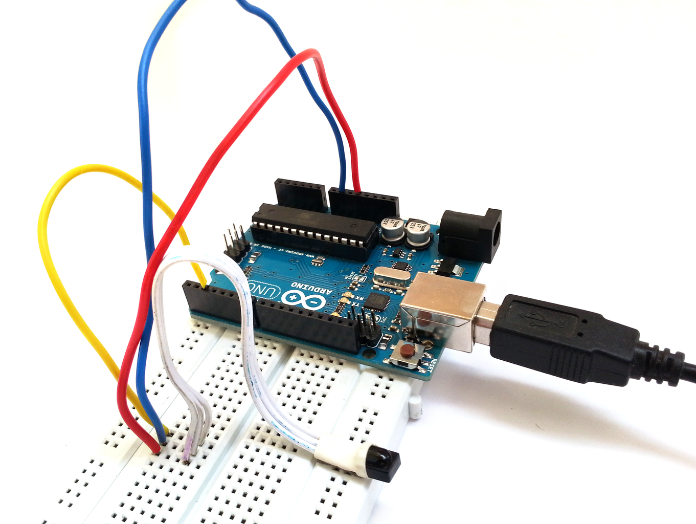
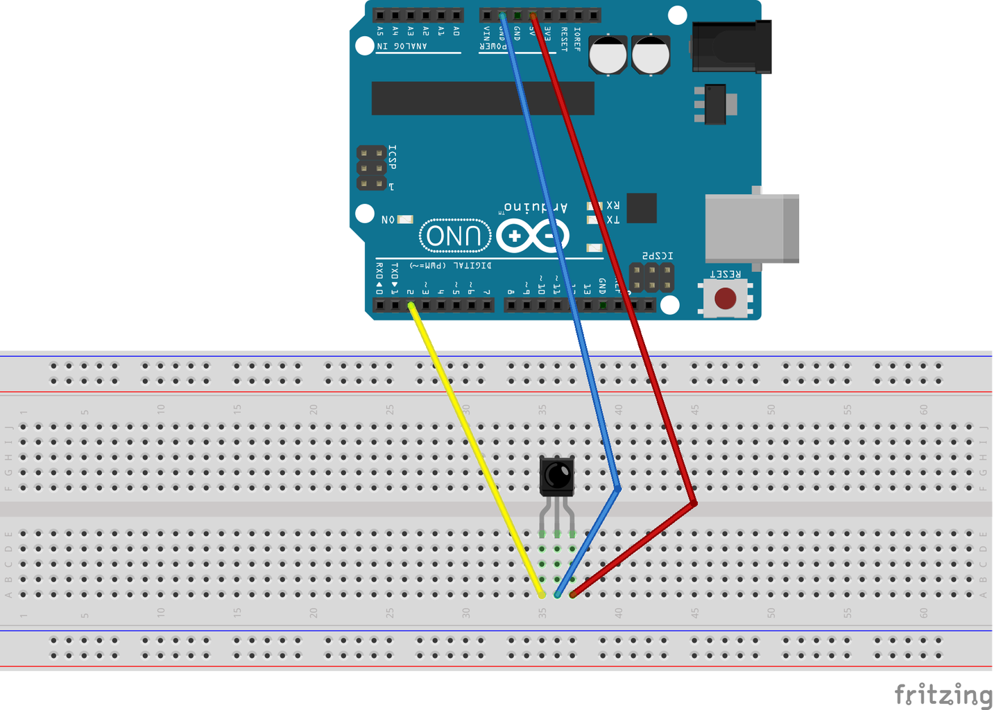

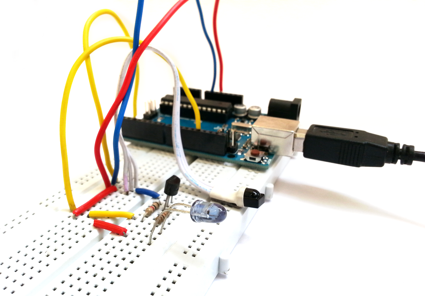
Now let's get to the interesting stuff. Connect your IR sensor to Arduino as shown in the image. I soldered some longer wires to my IR sensor and covered the joint with heat shrink. Make sure of the pinout of your sensor from its datasheet. Connect Arduino to PC and open up Arduino IDE.
I modified the code from this tutorial by ladyada to read a remote's IR codes so that it uses interrupts. Upload it to your Arduino. The .ino file is attached to this step.
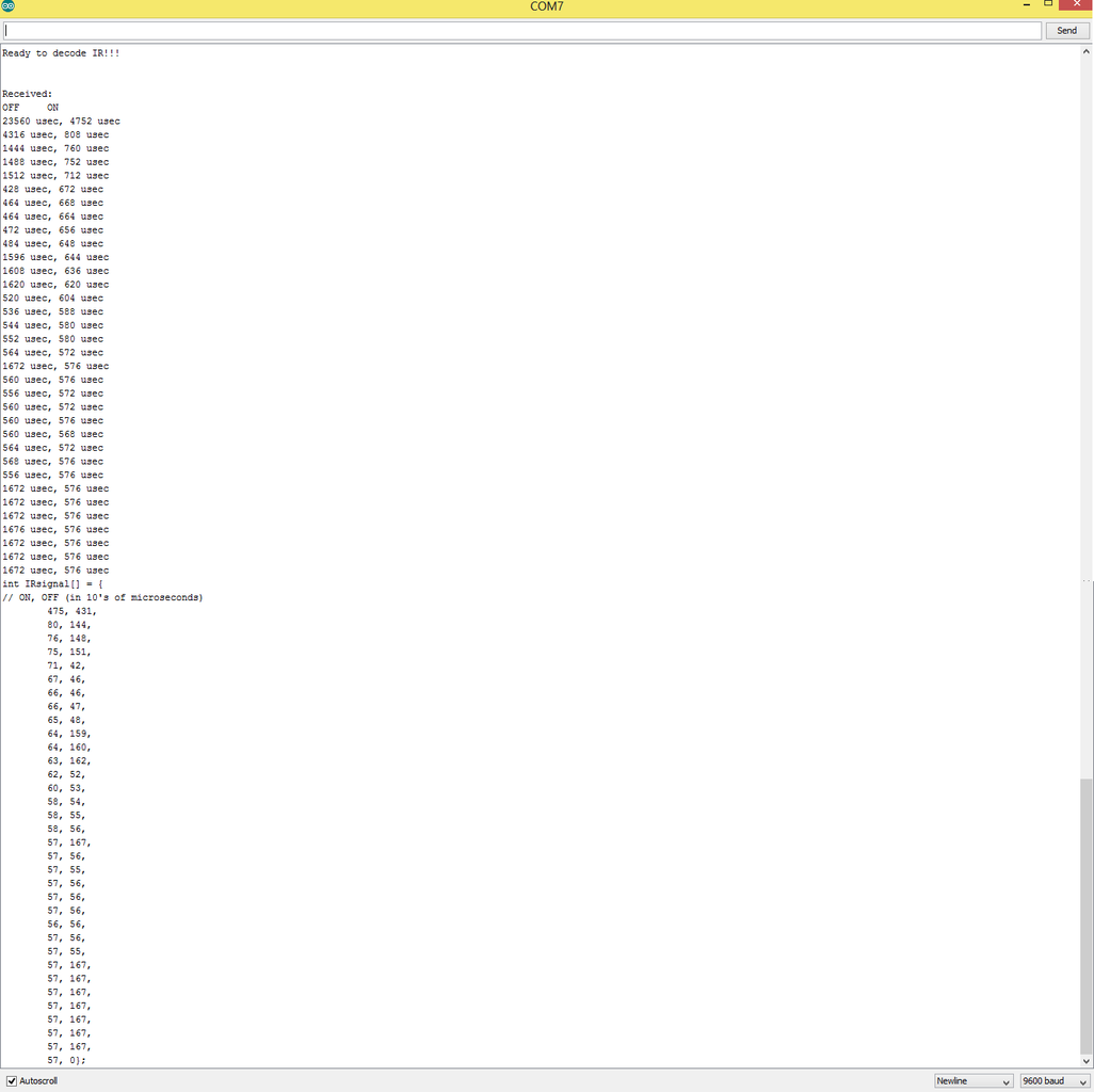
As I mentioned in the previous step, the remote code is nothing but how long the modulated signal was being sent and how long it was not. On your Arduino IDE's serial monitor, you'll get a series of OFF-ON duration. This is the raw data sent by the remote. If we had a remote sending the example IR code we used in the previous step, we'd have something like this:
Ready to decode IR!!!
Received:
OFF ON
1234 usec, 1500 usec
500 usec, 1500 usec
int IRsignal[] = {
// ON, OFF(in 10's of microseconds)
150, 50,
150, 0}
The first block of codes is the raw time values in microseconds, the second is the same values divided by 10 and presented in the form of a C array, so we can directly use it in our Arduino code(we'll use it while recreating the IR signal). Notice that raw value columns are OFF-ON and the formatted values are ON-OFF. The first raw data value (1234 usec) is useless as it is the measure of time there was no signal(OFF) before we started receiving the first ON signal (so doesn't appear in formatted values). In the values formatted as an array, last value will always be 0 as the last OFF duration will only end when you press a remote button again.
Attachments

Step 4: Decoding IR Signal Manually - Part I

Decoding IR signal implies mapping a different number to each button. So you can easily recognize the button by comparing the integer value representing that button instead of storing long IR codes for each button and comparing each value. To do this, we will process the IR timing values we got in the last step for each button. This step varies a lot from remote to remote. There are hundreds of remote protocols out there. This instructable aims to provide a basic understanding to cover most remotes, but the technique and codes can be modified to suit a complex one as well.
There will be a starting signal to your timing data. The starting signal is a unique ON-OFF pair value at the beginning to identify a remote. For my remote, it was: 8400, 4160. For some remotes, it might be more than a single ON-OFF value pair. Rest of the values(except starting code) can be usually grouped under 2 categories(about 20% difference is acceptable). All the values(besides start values) lies near to either 55 or 167 for my remote. If the starting code appears multiple times and the code which follows is always the same, then that means your remote is sending the same code over and over and you can remove the repetitive data.
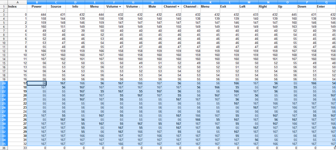
Now pick a spreadsheet editor of your choice. You can use excel or any similar software. I chose LibreOffice(free & open source!). Write down the button names for all your buttons in the column headings. Copy-paste the value for your first button IR code into the spreadsheet. You can use the delimit function to separate the ON-OFF values. Remember to delimit using commas and spaces so there are no leading or trailing spaces to your values, else they will be interpreted as text instead of numbers. Place the OFF values below the ON value in the same column after a gap of one row. Do the same for the next button. Look closely and bold those values in column-2 which vary from those in column-1 for the same row. A difference of less than about 15-20% can be ignored.
Do this for 3-4 more buttons. Usually, all the values that change from one button to another will lie in the ON list or the OFF list. We only need the values that change from button to button since that is the data. Mine were in the OFF list, so I removed all the ON values from the spreadsheet. Then I laboriously copy-pasted the OFF values for all the buttons. Remember to bold the values that differ from the previous column. In this way, we'll be able to easily visualize in which range all the data lies. My bold values(i.e. data) lies in the index 17-24 and 25-32. There is no data for index 24 and 32 as the number of buttons easily fit within 7 bits and so the 8th bit is unused, but I'll include it in my range as well.
Step 5: Decoding IR Signal Manually - Part II

You'll need to have a basic understanding of binary numbering system for this step, since the data being sent will be decoded in binary. Create a new sheet and copy the rows with data(i.e. ones with bold values). I replaced all the values nearby 50 to 0 and those near 150 to 1. You can choose the reverse as well. I used a simple formula: =FLOOR(B3/100, 1) to convert all values below 100 to 0 and all above to 1. Each row is a single bit in the byte data for the button.
It is clearly visible in the image that values in range 3-10 are the complement of those in 12-19 for my remote, i.e. wherever there is a 0 in 3-10, the corresponding value in 12-19 is 1 and vice-versa. So the remote is sending the same data for each button press twice, one being the complement of the other. Generally, there will be less than 8 bits of data per button. 8 bits(= 1 byte) is enough to represent 256 buttons uniquely.
Choose one of these ranges. I chose the range 3-10 as this yielded smaller values, but that doesn't make much difference. Convert the collective value in your range for each button to form a binary value. You can do it manually if you find formulas confusing. I used this formula to concatenate all the bits and form a binary number in row-21: =CONCATENATE(B10,B9,B8,B7,B6,B5,B4,B3)
Convert this binary to decimal. You can do it using a scientific calculator or use this formula in row 22: =BIN2DEC(B21) This final value you get is the decoded value for that button.
Step 6: Decoding Value Using Arduino Code

Use the attached code to decode the value in your program. A few modifications have to be made in the variables on top.
DATA_LOC : set this to 0 if the data values(which we highlighted in bold) are in OFF list, else 1 for ON list
LOW_VAL : the value you are taking as 0 for decoding
HIGH_VAL : similarly, the value you are taking as 1 for decoding
START_ON : the value for the start code under ON
START_OFF: similarly, the value for the start code under OFF
RANGE1_START : where to start reading values for decoding for the first range. Do not use the excel row number. The first row is 0, next is 1 and so on...
RANGE1_END: similarly, where does the last value for decoding liefor range 1?
RANGE2_START : if your values are duplicated, then where does the duplicated values begin?
RANGE1_END: similarly, where do they end?
RANGE2_INVERTED: are the duplicated values in range 2 the complement of values in range 1?
// IR DEFINITIONS
#define IRpin_PIN       PIND          // Pins for IR sensor (do not change)
#define IRpin           2             // Pin number for IR sensor (do not change)
#define DATA_LOC        0             // Data located in which list? 0: OFF, 1: ON
#define LOW_VAL         550           // Value to interpret as 0
#define HIGH_VAL        1560          // Value to interpret as 1
#define START_ON        8500          // Start code's ON value
#define START_OFF       4200          // Start code's OFF value
#define RANGE1_START    17            // From which index to start decoding?
#define RANGE1_END      24            // Till where to decode?
#define RANGE2_START	25            // comment this #define if you do not have repeated data
#define RANGE2_END 	32            // comment this #define if you do not have repeated data
#define RANGE2_INVERTED	1             // is range2 inverse/complement of range1? 1: yes, 0: no
#define MAXPULSE        65000         // the maximum pulse we'll listen for - 65 ms
#define MAX_PULSE_PAIRS 60            // maximum number of pulse pairs to store
#define FUZZINESS       5             // What percent variation is allowed: 2 = 50%, 3 = 33.3%, 4 = 25%. 5 = 20%
Why are we using the 2 ranges if they are the same, or just complement of each other? It's just an extra check to see if both matches. Comment out #define for RANGE2_START if you do not have a range 2 or don't want to use the extra check.
When you press a button on your remote, it will provide the decoded value for that button in the serial monitor.
Now your Arduino can know which button is being pressed. You can now assign different tasks to different buttons, such as turning an LED on and off with the power button, increasing/decreasing brightness with volume buttons, speeding up/slowing down blink speed with channel up/down buttons, etc.
Attachments
Step 7: Emulating IR Signals Using Arduino
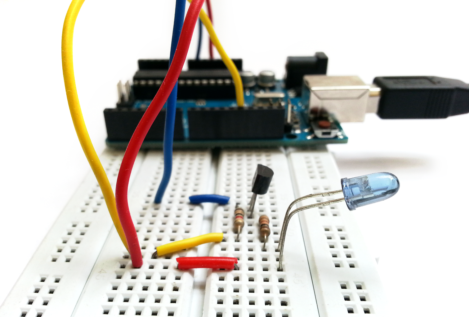


You can also send the IR signals using Arduino instead of using a remote. I modified ladyada's code so you can send code for any button by just providing its decoded value. This code will send the IR signal on reset and then after every minute.
To setup your own remote, choose any button from your remote and get the formatted C-array for it provided by the IR-reading Arduino code in Step-3. Replace the values assigned to uint16_t IRsignal[] array with the formatted array you got.
Now you can code it to send different IR signal by calling EncodeData() with the decoded value of the button you want to send as a parameter, and then calling SendIRCode(). For example you want to send IR signal for button whose decoded value is 2, call EncodeData(2) followed by calling SendIRCode(). As simple as that!
The attached arduino sketch waits for you to send the decoded value of the button you want to emulate and sends the IR signal for it. Remember to set line ending in serial monitor as 'Newline'.
Attachments
Step 8: Reading IR Using Raspberry Pi


Reading and decoding IR signals using Raspberry Pi is extremely easy. We only have to use LIRC (Linux Infrared Remote Control) and it will handle the most of the heavy lifting work for us. So let's get started...
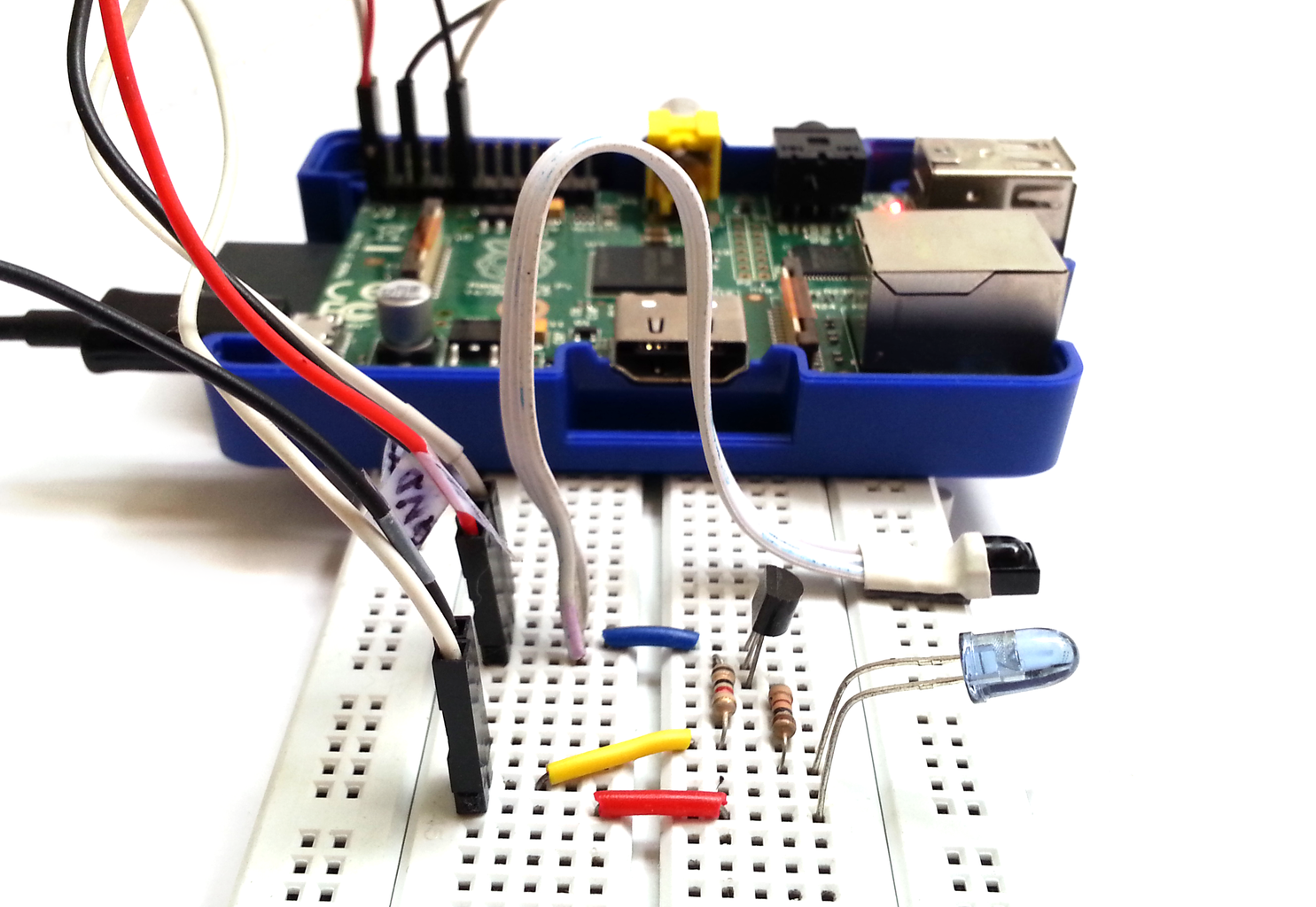
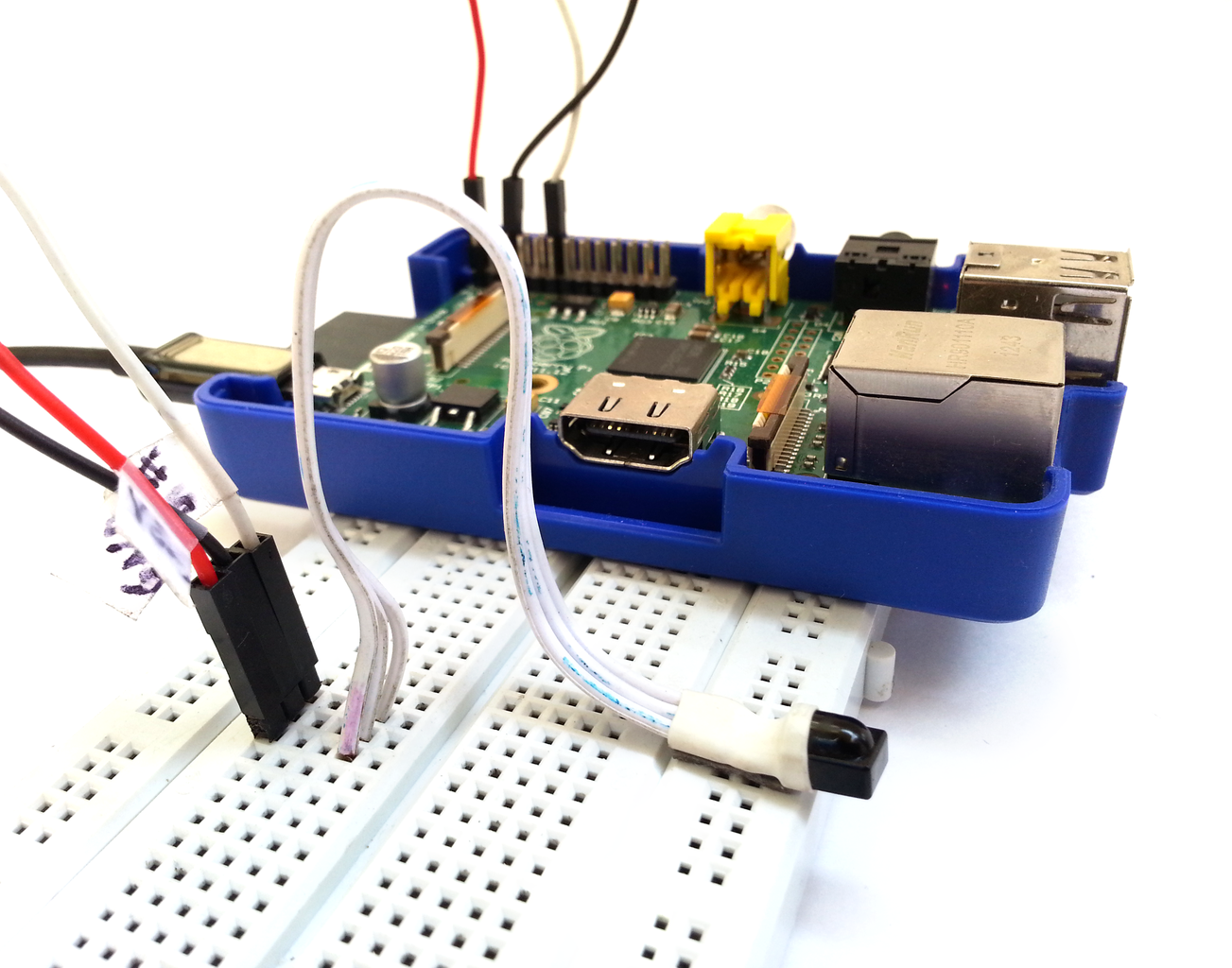
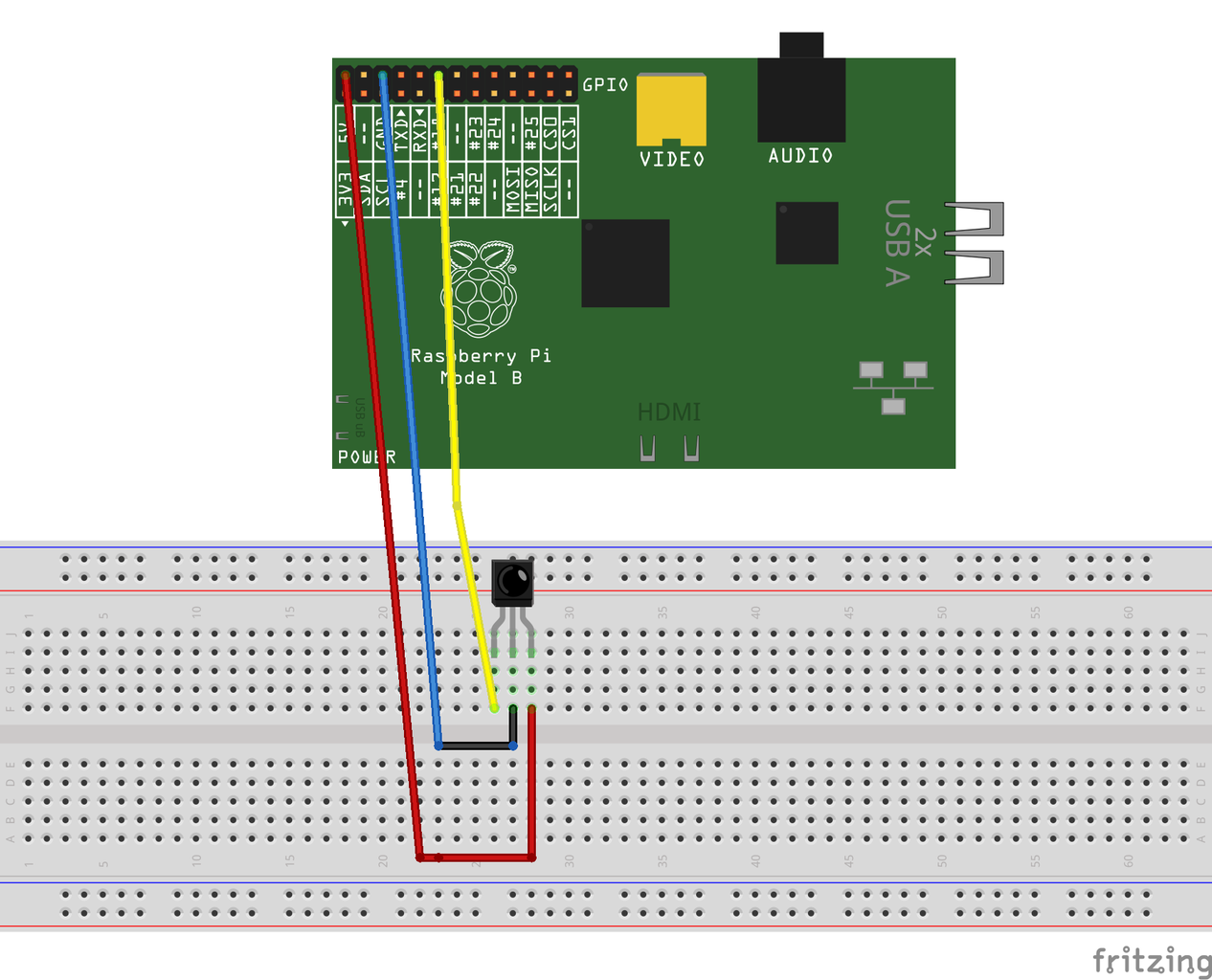
Connect an IR receiver to your Raspberry Pi as shown. IR sensor needs to be connected to 3.3V instead of 5V. We are connecting the data pin of IR sensor to Pin-18 of Raspberrty Pi.
Power up your Raspi, make sure you have internet connected.
Upgrade RPi2 firmware to newest version using these commands in order:
sudo apt-get update
sudo apt-get upgrade
sudo rpi-update
sudo reboot
After reboot, type the following command to install LIRC:
sudo apt-get install lirc
Open the /etc/modules file:
sudo nano /etc/modules
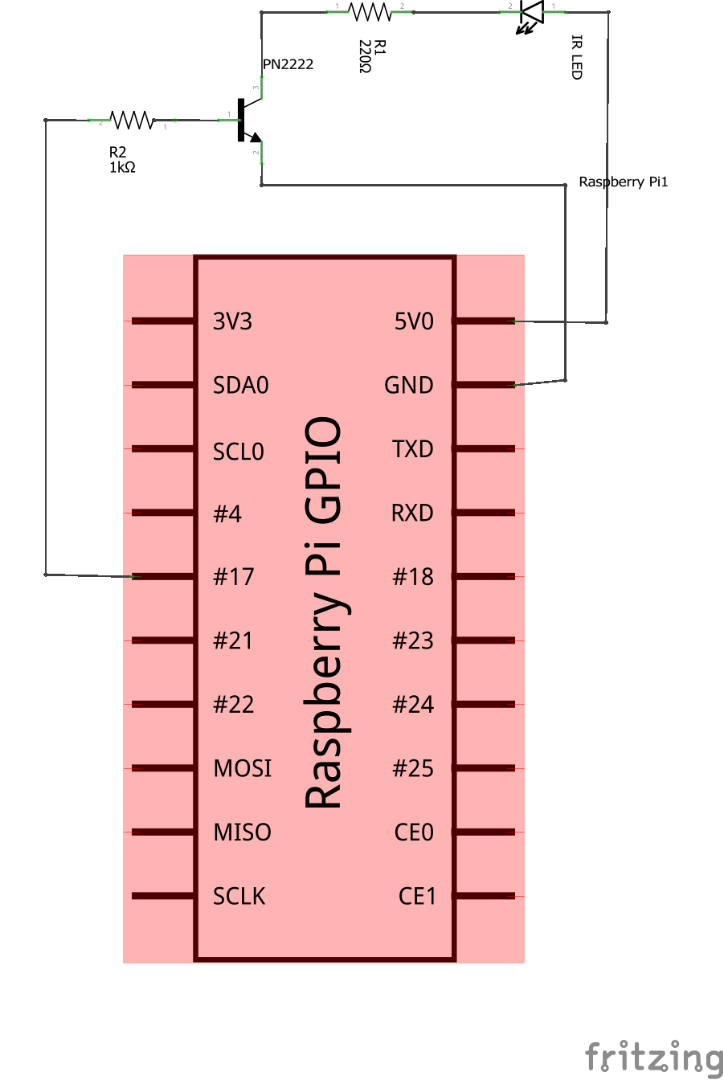
and add these lines at the end to make LIRC start up on boot and set the IR sensor pin to Pin-18 and IR LED pin(for later) to Pin-17:
lirc_dev
lirc_rpi gpio_in_pin=18 gpio_out_pin=17
To save, press Ctrl+X -> y -> Enter
Now we need to edit the LIRC hardware configuration file. Open it using:
sudo nano /etc/lirc/hardware.conf
Change the following lines:
DRIVER="default"
DEVICE="/dev/lirc0"
MODULES="lirc_rpi"
That's it! To make it work, you need to reboot your Raspi once:
sudo reboot
Note: buda.suyasa found out that to make LIRC work on Raspberry Pi 2, you need to edit /boot/config.txt using:
sudo nano /boot/config.txt
add the following line to it:
dtoverlay=lirc-rpi,gpio_in_pin=18,gpio_out_pin=17,gpio_in_pull=up
Step 9: Reading and Recording IR Signals Using Raspi


To check if your Raspberry Pi is reading IR sensor properly, you need to first stop the LIRC daemon(don't worry. There's no demon, it's just a fancy linux name for a background running process):
sudo /etc/init.d/lirc stop
To run a program to get the IR signal timings(similar to our IR-reading Arduino code), use:
mode2 -d /dev/lirc0
Now point your remote at the IR sensor and it should spit out a series of pulse-space(aka ON-OFF) IR timing values. This means everything is working perfectly.
Let's record the button values. The daemon needs to be in stopped state for this to work as well.
First, get the list of allowed button names using:
irrecord --list-namespace
Run the below command to start recording IR signals for each button and assigning an allowed name to it:
irrecord -d /dev/lirc0 ~/lircd.conf
It will take you through some weird but detailed instructions. Follow them and you will end up with a config file storing IR signals for each button. You can view it using:
sudo nano lircd.conf
It's best if you replace the name field value in the header with something relevant (I chose samsungTV).
Replace the default blank config file with your remote's new config file:
sudo cp lircd.conf /etc/lirc/lircd.conf
We're done with recording.
To test it out, start the LIRC daemon:
sudo /etc/init.d/lirc start
Run the following command to get the button's assigned name whenever you press that remote button:
irw
Note: If you are getting multiple output per button press, you can add
suppress_repeat 2
in the /etc/lirc/lircd.conf file so it ignores the next 2 repeat values.
Step 10: LIRC With Python - Part I

Using LIRC with python is extremely easy. We'll use the bundled slidepuzzle python game to demonstrate. I'll use the arrow keys on my remote to move the tiles in game. I'll provide the finished file along with the simulate game I modified to play with remote as well.
Firstly, we'll need to make licrc config file. This file contains information on what string to send to python when a particular button is pressed. Create and open a file using:
sudo nano /etc/lirc/lircrc
Paste the following lines:
begin
button = KEY_UP
prog = slidepuzzle
config = up
end
begin
button = KEY_DOWN
prog = slidepuzzle
config = down
end
begin
button = KEY_LEFT
prog = slidepuzzle
config = left
end
begin
button = KEY_RIGHT
prog = slidepuzzle
config = right
end
Between each begin and end, button is assigned the button name, prog is the program name and config is the string to be sent. So when a button is pressed, LIRC sends config string to prog program.
You have to change the button names with 4 buttons names you assigned to your remote.
Step 11: LIRC With Python - Part II


To use LIRC with python, we need to import lirc module first. Open IDLE and open slidepuzzle.py. It should be in /home/pi/python_games. At the top with the other imports, add
import lirc
We need to create a connection to LIRC. For that, write the below line of code just before the main game loop starts:
sockid = lirc.init("slidepuzzle", blocking = False)LIRC matches the first parameter(slidepuzzle) with the prog value in lircrc and only returns button matches for them. the second parameter(blocking = False) tells LIRC that it should not stop the python code execution to wait for the button press.
Just before we go into the event handling loop, write:
codeIR = lirc.nextcode()
if codeIR and isValidMove(mainBoard, codeIR[0]):
    slideTo = codeIR[0]
LIRC stores the button presses in a queue. lirc.nextcode() removes the next value from queue and return it. So if we pressed the remote button assigned to KEY_UP, we will get a list containing the string up i.e. codeIR will be ['up'].
In the next line, we check if codeIR isn't empty and that the move we are trying to make is a valid one. If yes, we set slideTo to the returned string in codeIR. Since slidepuzzle assigns up, down, left, right strings to slideTo to make the blocks move, we directly assigned that string saved in lircrc's conf to make it move.
That's all. I've done the same with simulate.py python game and attached both of them. Enjoy the games with a remote!
Attachments
Step 12: Recreating IR Signals With Raspi

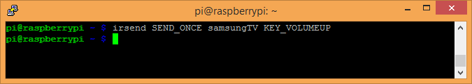
LIRC allows you to send the IR signals as well. If you have set up lircd.conf as instructed in Step-9, you can send IR signal for one of the recorded buttons using LIRC very easily. All you have to do is run the command:
irsend SEND_ONCE samsungTV KEY_VOLUMEUP
Here, replace samsungTV with the name of the remote you set in header of lircd.conf. KEY_VOLUMEUP has to be replaced by the name of the button you want to send.
If you wish to send the IR signal using Python, just import at the top:
import os
Now wherever you want to send IR signal, just call:
os.system("irsend SEND_ONCE samsungTV KEY_VOLUMEUP")
Participated in the
Remote Control Contest

Participated in the
Sensors Contest


