

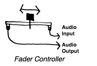
Introduction: How to Connect a Fader With Audio Input and Output


A fader is one of a basic component for mixing console. You can dynamically control your source with the movement of a fader.
There are already several way to use push buttons in your projects (e.g. hacking mouse and keyboard, or Arduino, gainer, MCK). This probides alternative way to use faders with audio input and output.
As side effects, it provides you with precious sampling resolution and frequency than the previous ways (i.e. 16bit to 8-10bit, 44.1KHz to 1KHz).
We present an application of this instructable from a work The SINE WAVE ORCHESTRA stay amplified.
All you need is just a fader, some soldering, and some software.
Note: This is for variable resistor type faders only. This will not work on optical type.
Note2: This is a series of "How to coonect with Audio". Please see others: Button, and Sensor.
Step 1: The Parts

You need to have a fader before you start. It could be find from your broken mixing console, or from electronic components store (e.g. RSin UK, Digi-Key in USA, Marutsuin Japan) with its alternative name 'potentionmeter'. All of the other components can be found at your local electronics shop (e.g. maplin in UK, RadioShack in USA, Tokyu-Hands in Japan).
1 Fader
The fader should be a variable resistor type. It has three (or even more) connectors and change its resistance with the position of the fader. Some mixing console use optical fader (mostly for DJ cross fader) and it doesn't work with this instructable. In this time, we use 'PROFADER SVA-1100' from TOKYO KO-ON DENPA. It has a very smooth movement.
2 3.5mm Mono Plug
One for audio input and another for audio output.
1 Twin Cable
You could use loudspeaker cable for this purpose. The length depends on how long you want.
1 Heat Shrink Tube
To cover the connector of the fader.
Step 2: The Tools

These are standard tools for assembling this project. I borrow part of the list from greyhathacker45's great work, thanks!
Soldering Iron
Solder
Multimeter
Wire Strippers
Nippers
Solder-sucker
Helping Hands
Clipped Cables
Step 3: Cutting the Cable

Let's have two pair of cables and strip the ends.
Step 4: Check the Fader

Before soldering, you need to check the connector of the fader. Most fader has three connectors. Two behave as a resistor and one for ground. You could find proper connectors by the change of the resistance with multimeter.
Step 5: Soldering the Fader (1: Resistor Side)

Now you ready to solder the fader to the cables. Each one side of two cables to be solder to each resistor side of connector. If the cable has a marker for one side, it would be better to use same part for the resistor side. Before soldering, do not forget to put your heat shrink tube! The cutting side of the cable needs to be twisted to avoid expanses. After soldering, the connector need to be covered with heat shrink.
Step 6: Soldering the Fader (2: Ground Side)

Next, you ready to solder the ground side. Before soldering, each cutting side of the cables needs to be twisted to avoid expanses, and do not forget to put your heat shrink tube!
Step 7: Soldering the Plugs

Then you ready to solder the plugs to the each end of the cable. Before soldering, the plug cover needs to be installed in the cable . The cutting side of the cable needs to be twisted to avoid expanses. After soldering, just attach the cover for the plugs.
Step 8: Quality Control

Now you have a set of a switch, two plugs, and a cable. Using multimeter on the resistance between the plugs. Tips (upper side) should be changing with the position of the fader and grounds (lower side) should be zero.
Step 9: Connect to the Audio Input and Output


Now you have a working hardware, so lets connect each side of the plug to the audio input and output.
Step 10: Some Software

Open your programming environment (e.g. MaxMSP, Pure Data, Flash, SuperCollider). If it could treat audio input and output, any environment is ok.
In this time, we use MaxMSP.
Assign an audio signal (e.g. 10000Hz sine wave) for audio output.
Set volume calculator for audio input. In this time, we use 'peakamp~' object.
Add a receiver for the calculator. In this time, we use 'multislider' object.
Here is a basic example of MaxMSP patche.
MaxMSP: fader-001.maxpat
Attachments

Step 11: Moment of the Connection

If it does not work, you just need to adjust the volume for audio output.
Step 12: Uses? Sine Wave Oscilator


Here is the setup. You will need split you audio output with stereo to dual mono cable. On one channel you connect the fader, and on another, you connect a speaker. Then you add a sine wave oscillator and a scale changer to fit the value frome fader to the frequency of the sine wave oscillator in your software. Now, you can finely control the sine wave oscilator in 16-bit resolution.
Here is a MaxMSP patch.
MaxMSP: fader-002.maxpat
Attachments
Step 13: Application: the SINE WAVE ORCHESTRA Stay Amplified
We detect the resistance of a fader controller as the amplitude of audio signal.
Step 14: Possible Improvements and Modifications
Though the sampling resolution of the movement is 16-bit or more (if you use external audio interfaces), you can use this instructable for controlling precious parameters (e.g frequency of oscillator).
As the fader is one of a variable resistor, you can use other types of resistors instead (e.g. shaft, CDS)
You can use two faders with 3.5mm stereo plugs and triple cable.
If you need more faders, you can extend with external audio interfaces. In this time, you need to use proper plugs for the port of the audio interface.


