

Introduction: How to Design a Fidget Spinner


There's no shortage of fidget spinners on the internet, but here's an instructable to show you how to design your own in Fusion 360.
I led a series of webinar classes related to 3D modeling projects that have moving parts. In these webinars, you will learn Fusion 360 features like advanced mechanical assemblies (meaning two or more joints interacting) and rendering.
Lesson 1: Fidget Spinner is a simple project that uses three 3D-printed parts and a bearing from McMaster-Carr. Here you'll learn how to use the McMaster-Carr part browser, basic 3D modeling, and how to make mechanical joints.
I cover all these techniques in this Instructable, but you can also watch this video of the webinar to see me model this project in real-time:
If you're interested, check out the other two webinars in this series where you will learn to design a Giant Knob Lamp and a Perpetual Clock with Arduino.
Step 1: Modeling Demo + Files
If you're new to Fusion 360, please sign up for my 3D Printing Class to get crash course in using the program.
Fusion 360 is free for students and hobbyists, and there's a ton of educational support on it. If you want to learn to 3D model the kind of work I do, I think this is the best choice on the market. Click the links below to sign up:
This video is step-by step demo (with no audio) of me modeling the spinner. The rest of the instructable has text and images explaining what I'm doing in each step.
If you just want to print your own or modify the one I made, I've attached STL files (ready to print) and an F3D archive file that you can import into Fusion.


Step 2: Import Bearing Model

Fist, you'll need to insert a 3D model of the bearing you're going to use make the spinner. Fusion has a McMaster-Carr part insertion feature that makes it super easy to work with super accurate 3D models of parts you can order from them. McMaster is a vast resource for manufacturing and making in general. They sell everything from plastic sheets to conveyor belts, and for many machine parts (and pretty much every fastener) they have 3D models that work as though they were made in Fusion.
To insert the part, go to INSERT>Insert McMaster-Carr Component.
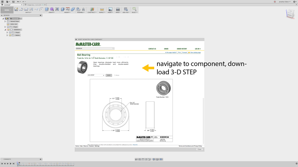
The MsMaster-Carr browser will come up. The categories can be pretty overwhelming at first, but just remember that bearings are found under Power Transmission. The I used is a 1/2" shaft open bearing that costs about $8. You could make this with just about any bearing you like. If you want to use this one, you can avoid browsing altogether and just type "6383K34" in the search field at the top, and the bearing I used will come up.
Select "3-D STEP" under the file type menu, then click Save.

Fusion will then create a new component with the part number as the name. This makes it easier for you to order the right parts when you're ready.
Step 3: Create Joint
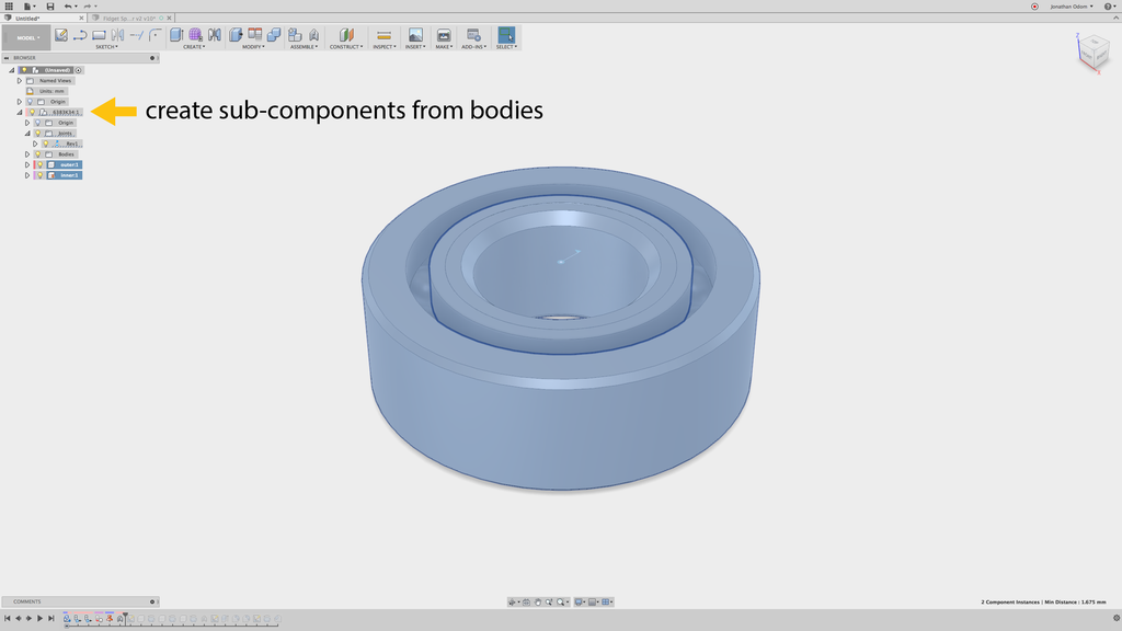
The part will come in as a component with a series of bodies in it. I want to simulate the movement of the mechanical joint within this part so I can see how my spinner will move, so I'm going to need to make some sub-components.
First, I right-click on the the component and select Activate from the drop-down menu. Next, I expand the Bodies in the activated component, then select each body to highlight them in the canvas. This way, I can find the two components I need- the inner ring of the bearing and the outer ring. When I find these, I right-click on them and Create Components from Bodies. This will give me two new sub-components.
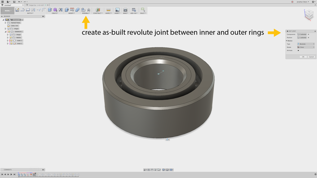
Now that I've got components, I can make a joint. I go to Assemble>As-Built Joint to make a joint between the two parts without moving anything. I select the inside ring component, then the outside ring component, then I pick Revolute from the Type drop-down menu. This will then give me a cursor that lets me pick the center of rotation. I can click on any one of the ring edges in the model and it will give me the proper center.
I don't want to make a Joint because the model is already correct, and a Joint will move parts around.
Finally, I need to Ground the inner ring component by right-clicking and selecting Ground from the drop-down menu. This will keep the center in place and let me click-and drag the outer ring to see it move.
Step 4: Create New Parts

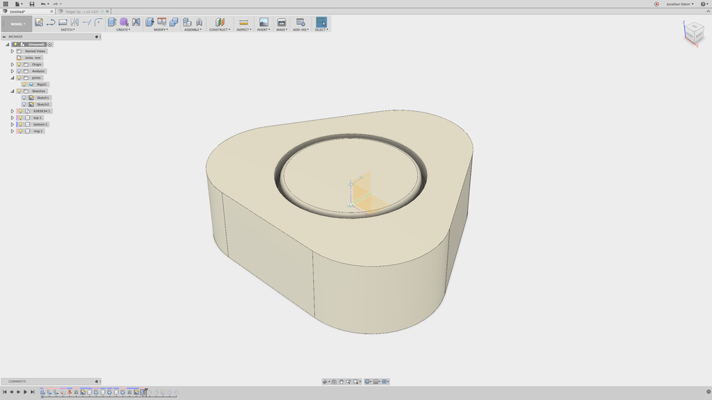
Now that I've got my bearing in place, I need to model the profiles of my parts. I create a sketch in one of the planes that bisects the part (the Front or Right plane will do). Next, I go to Sketch>Project/Intersect>Intersect and click on the bearing rings. this will give me profiles I can work from.
As you can see in the video, I drew all of the part profiles in one sketch based on the geometry of the bearing. There's a top cap, a bottom cap, and an outer ring. The outer ring has a little ledge (at the bottom in this view) that stops the bearing when it's pressed into the part- this keeps it centered. The top cap is a little ticker than the lower one because of this ledge on the outer ring.

Remember that to make radially symmetrical parts like this, you only need a people (half of the part in cross-section) and an axis to revolve around. The profile I drew above has all the profiles I need to revolve. I go to CREATE>Revolve to revolve the cap profile with the centerline selected as the axis. The type here should be New Component, not Joinwhich will be the default.
Remember that when you create 3D geometry from a sketch, your sketch automatically hides. You'll need to find it in the Browser and turn it back on to make the other two parts.

The model is now going to be kind of hard to understand in 3D because the bearing is now hidden by the other parts. To better understand your models, there's a great feature I use all the time called Section Analysis. Go to Inspect>Section Analysis and select one of the vertical origin planes.

Now you'll see a cross-section of your model cut where the selected plane is. You can turn the section analysis on and off by toggling the light bulb in the browser.
Step 5: Create Rigid Joint
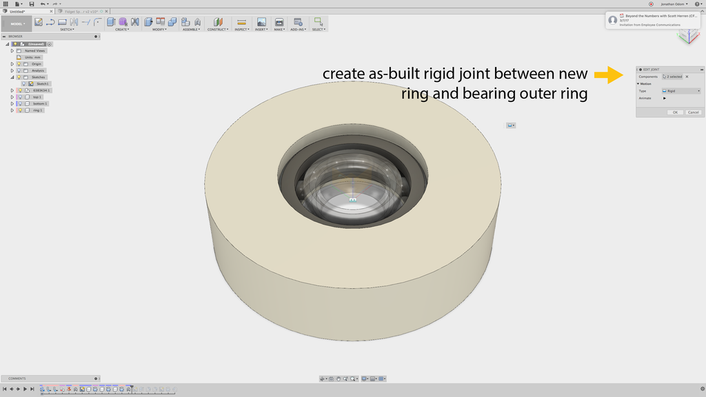
Since you've already got your revolute joint (on your bearing sub-components), you just need to create a rigid joint between the new ring and the outer bearing ring. Go to Assemble>As-Built Joint again, select these two components, and select Rigid as your joint type. This will make it so that if you click and drag the ring, it will spin along with the bearing.
Step 6: Create New Profile

This spinner will work just fine as is, but I've decided to give it a new profile to make it more fun. I made three big circles using Polar Array in the Sketch menu to create the profile, but you can use any shape you like. The piece will still spin as long as the new shape is radially symmetrical.
Try making a polygon shape by selecting SKETCH>Polygon>Inscribed Polygon, for example. You can change the number of sides and make an octagonal profile if you want.

When you've finished your profile, go to CREATE>Extrude and select the profiles you want to use to cut.
My spinner now has a rounded triangular profile.

To make it more attractive and smoother to the touch, I go to MODIFY>Fillet to round off the edges of the ring.
Step 7: Create Cap Indentations
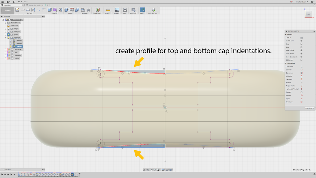
To make the part even more comfortable, I added some indentations to the caps. To do this, I create another sketch on one of the vertical origin planes, then go to SKETCH>Project / Include>Intersect and select the two cap bodies to give me some lines to work from. I draw tangent lines from the circles I added at the ends of the profile, then go to SKETCH>Fillet to make a nice smooth profile.

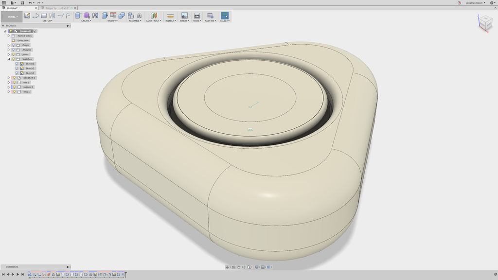
To cut this shape out of the caps, I go to CREATE>Revolve, select the profiles, then select the centerline as the axis. This should Cut the shape by default, which is what I want.

With the Section Analysis turned on, you can now see the finger indentations and the new triangular profile in cross-section.
Step 8: Save Parts for Printing

To save the parts, just right-click on each component in the Browser and select Save as STL. Of course, you don't need to save the bearing, since you'll buy that on McMaster.
Step 9: Slice the Model for Printing

With the parts saved as STL files, you can import them into your slicing software to prepare them for printing. I use Simplify 3D, but you can also get great results with Cura, which is free.

I placed the parts so that the top of the caps are facing up- that way I get the best possible finished surface even though it costs more material because of the support structures.
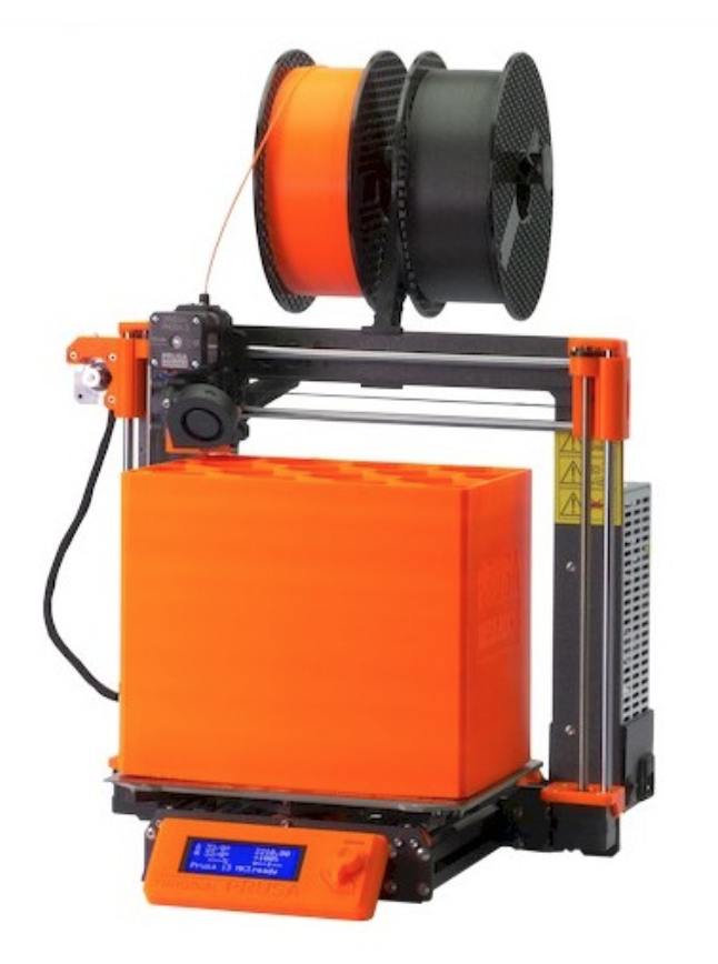
I use a Prusa I3Mk3S for just about everything. It's the best bang for your buck, in my opinion- very well made, 3D printable replacement parts, accurate and reliable.
Step 10: Assemble and Fidget

The assembly is really straight forward. The bearing is symmetrical, so it can be inserted with either side up (you may need a hammer to tap it in). Be sure you're inserting the correct caps in the top and bottom- the thinner one goes on the bottom to make room for the ledge.
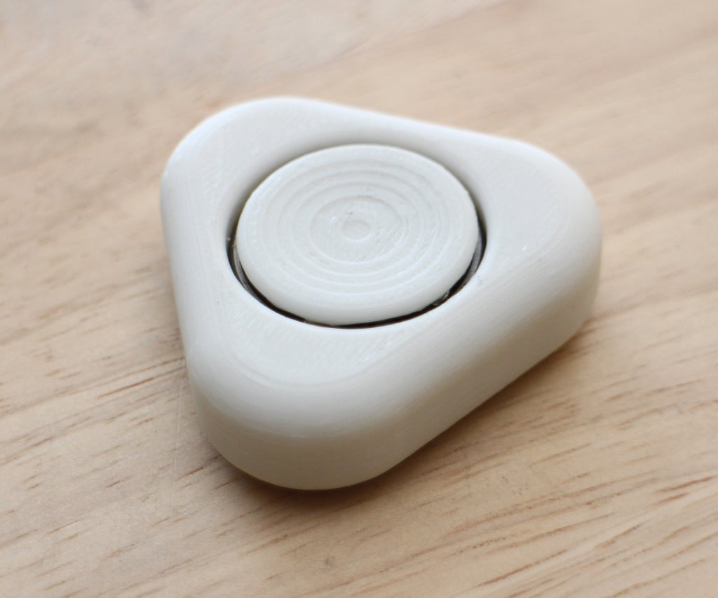
The gradual slope of the indentations on the caps create this stepping effect- this could be avoided with a steeper slope, but the look of this doesn't bother me.
It's a very satisfying action, and it feels comfortable in my hand. The denser the infill, the heavier it'll be, and the longer it'll spin. Have fun!


