

Introduction: How to Design the Best Wind Farm Blade in Tinkercad - a STEM Challenge & Lesson Plan for Teachers


This Instructable integrates a MyStemKits problem-based learning activity aligned to the NGSS and Common Core Standards. This model eliciting activity (MEA) will help students tackle real-world problems as they balance budgetary constraints with finding the most-optimal design, all while overcoming unforseen circumstances that may change the procedure students use to determine the best solution. In the end, students are challenged to design and test their own wind farm blades, using Tinkercad to model a 3D-printable blade.
Subject: Math
Strand: Geometry
Grade: 7, 8
Estimated Instructional Time: 5 class periods, 50 minutes each
Estimated Blade Design Time: 2 class periods, 30 minutes each
Lesson Plan Abstract:
In this middle-school engineering design
challenge, students are challenged to create the most efficient wind turbine while balancing cost constraints. Students will apply their knowledge of surface area and graphing while testing their 3D-printed designs using Tinkercad.
---
Materials:
- Computer with internet
- 3D Printer
- Strong Fan
- 4 #2 Pencils
- String
- Tape
---
Content and Practice Standards:
Common Core State Standards
CCSS.MATH.CONTENT.7.G.B.6 Solve real-world and mathematical problems involving area, volume and surface area of two- and three-dimensional objects composed of triangles, quadrilaterals, polygons, cubes, and right prisms.
CCSS.MATH.CONTENT.8.F.B.4 Construct a function to model a linear relationship between two quantities. Determine the rate of change and initial value of the function from a description of a relationship or from two (x, y) values, including reading these from a table or from a graph. Interpret the rate of change and initial value of a linear function in terms of the situation it models, and in terms of its graph or a table of values.
MAFS.8.SP.1.1 Construct and interpret scatter plots for bivariate measurement data to investigate patterns of association between two quantities. Describe patterns such as clustering, outliers, positive or negative association, linear association, and nonlinear association.
CCSS.MATH.PRACTICE.MP1 Make sense of problems and persevere in solving them.
CCSS.MATH.PRACTICE.MP2 Reason abstractly and quantitatively.
CCSS.MATH.PRACTICE.MP4 Model with mathematics.
CCSS.MATH.PRACTICE.MP5 Use appropriate tools strategically.
CCSS.MATH.PRACTICE.MP6 Attend to precision.
CCSS.MATH.PRACTICE.MP7 Look for and make use of structure.
NGSS Science and Engineering Practices
- 1. Asking questions and defining problems
- 2. Developing and using models
- 3. Planning and carrying out investigations
- 4. Analyzing and interpreting data
- 5. Using mathematics and computational thinking
- 8. Obtaining, evaluating, and communicating information
Step 1: Prepare for 3D Printing

You will need to download our pre-designed blades and stand so you can 3D print and test them as part of the lesson plan associated with this project. The Model Guide with part information and the .stl files are attached here for you to download. Use the provided layouts (whichever set fits on your print bed) or open the files in your preferred slicing software and arrange them to fit on your printer. If creating your own print layouts, be sure to include the following amounts:
- 1x Stand Top (WFM-STP-0817)
- 3x Stand Foot (WFM-SFT-0817)
- 1x Spool (WFM-ASP-0817)
- 2x Centerer (WFM-ACN-0717)
- 1x each Sample Blade (4 total) (WFM-{R3S, R8L, P5S, P12}-0717)
- 3x Weight (print at 100% infill) (WFM-SWT-0717)
The weights should be kept separate and printed at 100% infill. The rest of the parts can be printed together at a low infill setting (15%). For all parts, 0.3mm/layer is a good layer height. If you are printing using PLA, you should not need a brim, raft, or supports.
You can also view the original Tinkercad file here.
If you already subscribe to www.MyStemKits.com, you can also print these directly from our website. Simply search for "Wind."
Attachments


Step 2: 3D Print

Once you've prepared your slicer settings, begin your print. Depending on your printer, you may be able to print directly from the software if the printer is connected to your computer, or you may need to transfer your slicer-generated files onto a USB or SD card to print them. Refer to your 3D printer's documentation.
Remember to make sure to print the weights at 100% infill.
Once the models are done printing, break off the support for the weights and any rafts, brims, or supports you/your printer may have added.
Step 3: Follow the Model Guide and Lesson Plan
The Model Guide provides step-by-step instructions on assembling the 3D printed parts.
The parts may be a tight fit on the pencils. It is okay if some of the yellow paint on the pencils is removed as it is assembled.
Follow the instructions in the lesson plan for how to test the pre-designed blades. In the next steps, you will design and print your own blades to test and improve the design.
Step 4: Design Your Own Windmill Blade Using Tinkercad: Part 1 - Planning

Before you start modeling your blade, you'll want to design it on paper first.
Choose the shape, then decide what you want the parameters of the shape to be and how many blades you want.
Using the graph paper provided in the lesson plan, draw the profile of your blade.
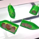
The image shows the different blade shapes as a side view of a single blade at 90 degrees (upright).
Step 5: Blade Design: Part 2 - Setting Up the Workspace


Open a new workspace in Tinkercad and add a ruler to help position parts. The ruler can be positioned anywhere but positioning it on the bottom left corner may be most intuitive.
Change the ruler to midpoint mode by clicking the icon under the x which appears as a circle with 3 lines inside it.
The ruler will let us position parts relative to a fixed location and changing it to using midpoint means we can easily center all our parts on the origin of the ruler instead of an arbitrary point or the center varying depending on the size of the blade.
Step 6: Blade Design: Part 3 - Making Your Blade


Drag in the desired blade type from the featured shape generators menu in the sidebar. (You can also open the original Tinkercad file and edit from there by ungrouping and regrouping.)
Position the midpoint of the blade on the ruler by changing the distances from the ruler to 0. Leave the upward distance where it is even though it is not zero.
To make the blade that you designed a couple steps ago, use the sliders or type in numbers to match your dimensions. The angle of the blades can be changed but it is advised to leave it at 45 for print reliability and performance.
If you set an odd number of blades, you will notice the blade is no longer centered on the ruler origin. This is okay. The hub is still centered but since the blades are no longer symmetrical on the ruler axes, the center of the part overall has changed.
Step 7: Blade Design: Part 4 - Cutting the Pencil Hole


Next, we need to cut a hole in the middle of the hub
Drag in a polygon from the basic shapes menu in the sidebar. Make sure the shape is a regular hexagon with 6 sides.
Resize the hexagon to 8.25 in the longer direction (point to point) and 7.145 in the shorter direction (flat to flat). You can do this calculation yourself or with an online calculator if you want but this size should work to fit tightly onto the end of a pencil.
Change to hole instead of solid and center it the same as the blade by changing the distances from the ruler to 0.
Step 8: Blade Design: Part 5 - Flattening the Base


In order to print cleanly, we want to make sure that our part has a flat base. To do this, we will make a box to remove any material below the workplane.
Drag in a box hole from the basic shapes sidebar menu.
Change the height of the box to 2 and the upward distance to -1. Because we are measuring using the distance between the ruler and the midpoint of our box, this puts the top edge of the box on the workplane and will remove material below the workplane.
Position the box in the same way as the blade and hexagon, then expand it until it is larger than the blade.
Expand the box typing numbers, not by dragging so that it stays in position.
Step 9: Blade Design: Part 5 - Grouping, Exporting, and Printing


Finally, select all the parts by clicking and dragging a box around them or holding shift and clicking each part and combine them by clicking group. If you want to modify your design still, you can click the ungroup button or double click on the part to make changes then hit escape and they will stay grouped.
Now that you have a single part with the pencil hole and flat base, you need to export it as an stl. Click the export button in the top right.
This opens a dialogue box. Since there is only one part here, there is no difference between the "Everything in the design" and "The selected shape" options, but if you had another part in it, make sure to select the part you want to export and use the selected shape option. Click .STL and you will download an STL of our blade. Move it from downloads to the folder with the rest of the parts to keep everything together then print it on your 3D printer.
Step 10: Test and Revise

Replace the blade on your stand with the one you designed and test it according to the lesson plan. See how it compares to the other designs, make changes and repeat to optimize your design.
Hope you have had a blast exploring different wind farm designs and the challenges in designing the perfect blade! Feel free to go back to the drawing board and finesse your designs further. After all, you're engineers now. The sky's the limit!
This activity is brought to you by www.MyStemKits.com, the world's largest library of vetted 3D-printable models and standards-driven lesson plans designed specifically for K-12 STEM education. Our focus on real-world, hands-on learning has been designed to promote deep conceptual understanding so students are equipped to succeed in the 21st century. By providing lesson plans such as this one, we help the students become their own designers and out-of-the-box thinkers solving complex problems using the power of 3D printing.


