

Introduction: How to Make Your Own Plasma Cutter....


Check out new video of the Plasanator on utube.com
This Ebook is designed for Guys and Gals who like to create tools and machinery.
I hope my Ebook gives you hope that no matter how hard a project may seem, keep plugging away until you finish and you will succeed.
I spent 3 years putting this together and now finally all my hard work and research has paid off.
I studied diagrams from commercial venders, but to no luck. They tend to leave a lot out – on purpose - so it’s hard to reproduce their design. I’ve see different attempts at people making their own on You Tube and other sites, but what a death trap. Messy water resistors and wiring like a darn Christmas tree.
So I began reading books and articles on their workings and took my home schooled-knowledge of electronics to build my own plasma cutter. I was determined; failure was not an option.
I started by collecting parts from old microwaves, stoves, water heaters, air conditioners, car parts and more in the hopes of creating a low budget way to create a plasma cutter for myself. I mounted it all on a simple piece of scrap wood; well it’s scrap wood now. We, didn’t need that table anyway (shhhhhhh don’t tell the wife).
Then one day it all came together. I hit the power switch, placed the head to the metal, started the arc, felt the air kick and then a second hard kick (the current being drawn into play). Then BAM, it was slicing through quarter inch steel like a hot knife through butter.
How sweet it sounded! I felt the amazement of completing a project that I just couldn’t let go of.
So, take your time, enjoy and be safe.
The Plasmaman
P.S.
Like Steam Punk?
Check out my Tesla Levitating Steam Punk Lamp Video. Also my Thingaverse projects you might like about 3d printers.
https://www.thingiverse.com/plasanator/designs
https://www.youtube.com/watch?v=jip8HYd39g0
Step 1: Assembly

When I started assembling my cutter, I began with taking a good look at my parts. As shown in Section 5 and Section 6, my parts are laid out so I can begin checking off from my parts list. Once this was accomplished, I would study each the parts pictorial to get familiar with each part/component and they would be placed.
The next step was to study my schematic and create a layout diagram. My board layout diagram is the most valuable piece in the building, repairing, and modifying process of my cutter.
As I began mounting my parts, I organized my board into four sections. Those sections are Power Control, High Current DC, Low Voltage DC and High Voltage Arc Start.
Power Control
3KVA step down transformer and contactor. The transformer is mounted off board because it is big and heavy, as you can see in Section 13. The contactor became my first part on the board. I wired it so when the head trigger is pressed, it turns the contactor on and allows my DC components to come on line. Then I began with my next system, High Current DC.
High Current DC
Bridge Rectifier
Large Capacitors
Reed Switch (which I used as a current sensor), what it does is allow the high voltage arc system to fire and as soon as high current starts to travel to the head and cutting starts it shuts down the high voltage arc system while cutting since it’s not needed at this point.
If you lose your fire it restarts the arc and gets you going again automatically.
My next system was placed on board.
Low Voltage DC
The low voltage DC components are mixed with power switch and 120 volt terminals.
Power Switch
120-volt terminal blocks
12 volt transformer
Low voltage bridge rectifier
Auto relays
Terminal strip, 4 position is all I needed but 5 position was what I had in my toy box.
High Voltage Arc Start
Microwave capacitor or run capacitor, a household dimmer switch rated for 15 amps. A Ford or Chevy ignition coil. I used the Chevy on this cutter. As you can see, I have terminals to all parts that get an external connection outside of their system so all I have to do is run a piece of wire in-between. Now look at the pictorial of board mounted parts in Section 11. It shows all the wires on the board, but here you can see all terminals and parts mounted, as I wanted. When wiring all my components, I used my Chevy board layout diagram to run my wires.
I checked and re checked all wires before mounting external parts. If you go to the final wiring section, you will also find pictures of my rigging of these parts. I could have done it many different ways, but this is what I chose at this time.
It took me about 3 hours of procrastination to finally assemble it all. You know how it is on a project, once you are ready with all your parts, your mind starts giving you a million ways of doing something. And, at last you just pick a way and go with it.
Once I got it all together, I connected my air tank hose and put the pressure setting at 28 for a safe point to start. I fired it up and BAM - that baby didn’t need any more adjusting. It was cutting!
You can imagine all the relief and pride I felt when the Plasanator started kicking ass. Yea, I said it Kicking Ass Baby. Oops Wife just told me I need to stop, hee hee and for all you creators – ah ah ah ahhhhhh.
I hope you enjoyed riding along with me in my journey.
Take care and be safe.
The Plasmaman
Step 2: Parts List

Parts List
Step 3: Warning Warning

Step 4: Schematic

Chevy Pictorial Schematic
Step 5: Another View

Step 6: Another Schematic to Looksy At

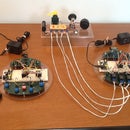
Step 7: Board Lay Out

Now this is to demenstrate how I set it up before putting it in a case configuration.
So dont think you would leave it like this for it would be to dangerous to do so.
Step 8: Transformer I Used

Its a control transformer I got off ebay for 50 bucks.
It's 220 to 120 3kva 25 amps and works great in power isolation.
Step 9: Transformer Connected to Board Terminals.

Step 10: Power to Contactor Terminals


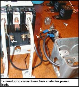


These are the contactor terminal conections on the transformer side and then the contactor to large bridge rectifier connections.
Also you will see Bridge rec to Capitor connections and how they are connected.
This is your Main Current set up.
Step 11: Reed Current Sensor


Step 12: Low Voltage Side


Step 13: Relay Connections by Color


Step 14: Chevy HV Transformer Connections


Step 15: Arc Tip Assembly to Head

Step 16: Head Air Coupling


here is where you will connect your air line to your head if you dont have a fitting to do so then hook to board connections.
Step 17: Air Filter/ Element and Solinoid Hook Up View

Just showing temp hook up.
Step 18: Final Power Connections


Ok now you can put all your final connections together and keep going over your schematic to double or triple check everything.
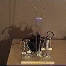
Step 19: Extra Photos of Past Cutter Projects


Here are some photos of past cutter projects for you to enjoy.
Now remember that you will need to put in a case for safty.
It can be would metal or plastic just enclose it.
My photos are in a testing stage and that is why you see them exposed.
The photos of the red cutter was a china one that burnt up on my neighbor and I ripped out the guts and replaced it with my design.
He just loves it.
The black box on side is the housing for 2 elements to draw more current.
You will also see here some other designs where I used a chevy control module as the hv arc start and my first plasma cutter on test stand using stove coils as current resistors.
Have fun and be safe ya'll. Joe
Step 20: Plasanator 3's First Cut

http://www.youtube.com/watch?v=nA6zWHNn6zU
Goto link and watch it's first cut while listening to the mission impossible song.
Thanks for stopping by and God Bless.

Participated in the
MakerBot Challenge


