

Introduction: How to Build Your Own Jet Engine

You don't have to be Jay Leno to own a jet powered motorcycle, and we will show you how to make your own jet enigne right here to power your wacky vehicles. This is an ongoing project, and plenty of additional info will be available on our website soon. See the full build at http://www.badbros.net
This information is brought to you by Bad Brothers Racing and Gary's Jet Journal
http://www.badbros.net
http://www.garysjetjournal.com
Warning! Building your own jet engine can be dangerous. We highly suggest that you take all appropriate safety precautions when dealing with machinery, and use extreme care while operating jet engines. Serious injury or death can occur while operating a jet turbine engine in close proximity, due to explosive fuels and moving parts. Extreme amounts of potential and kinetic energy are stored in operating engines. Always use caution and good judgment while operating engines and machinery, and wear appropriate eye and hearing protection. Neither Bad Brothers Racing or Gary's Jet Journal accept any liability for your use or misuse of the information contained herein.
Step 1: Come Up With a Basic Design for Your Engine

I started the build process of my engine with a design in Solid Works. I find it much easier to work this way, and creating parts using CNC machining processes turns out a much nicer end result. The main thing I like about using the 3D process is the ability to see how the parts will fit together before fabrication, so that I can make changes before spending hours on a part. This step is really not neccesary, as anyone with decent drawing skills can sketch out the design on the back of an envelope rather quickly. When trying to fit the entire engine into the final project, the jet bike, it will certainly help a lot.
I would also suggest that to get the best answer to questions if you are attempting to build a jet engine or turbine based project, subcribing to a user group is the way to go. The years of combined experience from various users proves invaluable, and I am a regular on the Yahoo Groups DIY Gas Turbines forum.
Step 2: Get Yourself a Turbo Charger and Hide Away in the Garage Building Your Insane Jet Powered Contraption!
Use care when selecting your turbocharger! You need a large turbo with a single (non-divided) turbine inlet. The bigger the turbo, the more thrust your finished engine will produce. I like the turbos off of large diesel engines and earth moving equipment. The use of one of these turbos will yield enough thrust output to move a vehicle of some sort pretty well. It is best to buy a rebuilt unit if possible. Ebay is the way to go here, as you can really save some money.
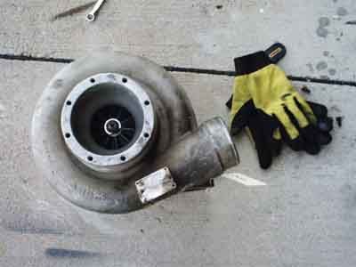
As a general rule, it is not so much the size of the whole turbo as it is the size of the inducer that matters. The inducer is the visible area of the compressor blades that can be seen when looking at the turbo's compressor with the covers (housings) on. Looking at the turbo here will show that the air inlet is quite large at almost 5 inches in diamter, while the visible blades of the inducer are only 3 inches in diameter. This is plenty for creating enough thrust to drive a mini motorcycle, go kart, or other small vehicle.
The turbo in the picture is a Cummins ST-50 off of a big 18 wheeler truck.
Step 3: Figuring the Size of the Combustion Chamber
Here is a quick rundown of the process of how the jet works and how to figure the size of the combustion chamber you will be making for your jet engine.
The combustion chamber works by allowing compressed air coming from the turbo's compressor to be mixed with fuel and burned. The hot gasses then escape through the rear of the combustion chamber to move through the turbine stage of the turbo where the turbine extracts power from the moving gasses and converts them to rotational shaft energy. This rotating shaft then powers the compressor attached to the other end to bring in more air to make the process continue. Any additional energy left in the hot gasses as they pass the turbine create thrust. Simple enough, but actually a bit complicated to build and get it right.
The combustion chamber is made from a large piece of tubular steel with caps on both ends. Inside of the combustion chamber is a flametube. This flametube is made of another smaller piece of tubing which runs the length of the combustion chamber and has many holes drilled in it. The holes allow the compressed air to pass through in certain ratios which are beneficial for 3 steps. Step one is mixing the air and fuel. The combustion process also begins here. Step to is to provide air for the completion of combustion, and step three is to supply cooling air to lower the temperatures before the airstream comes into contact with the turbine blades.
To calculate the flametube dimensions, you double the diameter of the inducer of your turbocharger, and this will give you the diameter of the flametube. Multiply the diameter of the inducer of the turbo x 6, and this will give you the length of the flametube. Again, the inducer of the turbo is the part of the compressor blades that can be seen from the front of the turbo with the covers (or housings) on. While a compressor wheel in a turbo may be 5 or 6 inches in diameter, the inducer will be considerably smaller. The inducer of the turbos I like to use (ST-50 and VT-50 models) is 3 inches in diameter, so the flame tube dimensions would be 6 inches in diameter by 18 inches in length. This is of course a recomended starting point, and can be fudged a little. I wanted a slightly smaller combustion chamber so I decided to use a 5 inch diamter flametube with a 10 inch length. I chose the 5 inch diameter flametube primarily because the tubing is easy to aquire as diesel truck exhaust pipe. The 10 inch length was figured because the engine will be going into the small motorcycle frame of the mini jet bike eventually.
With the size of the flame tube calculated, you can then find the size of the combustion chamber. Since the flametube will fit inside of the combustion chamber, the combustion chamber housing will have to be a larger diameter. A recomended starting point is to have a minimum 1 inch space around the flametube, and the length should be the same as the flametube. I chose an 8 inch diameter combustion chamber housing, because it fits the need for the airspace and it is a commonly available size in steel tubing. With the 5 inch diameter flametube, I will have a 1.5 inch gap between the flamtube and the combustion chamber housing. Try to use steel tubing instead of pipe when possible. The difference between 8 inch tubing and 8 inch pipe would be that the tubing would be measured at 8 inches outside diameter and you then select the thickness of the "wall" you need. I chose a 1/8th inch wall thickness for my engine. 8 inch steel pipe would have an inside dimension of roughly 8 inches and the wall thickness is determined by a schedule or strength number such as "schedule 40" or "schedule 80" Steel pipe tends to be much thicker in the "wall" than tubing, and can add considerably to the overall weight of the engine.
Now that you have the rough dimensions you will be using for your jet engine, you can proceed to putting it together with the caps on the ends and the fuel injectors. All of these parts combine to form the complete combustion chamber.
Step 4: Assembling the Combustion Chamber - Preparing the End Rings

To make the combustion chamber result in a simple bolt together piece, I use a method of constructing rings that will not only provide a surface to which the end caps can be bolted, but they will also hold the flametube centered in the combustion chamber.
The rings are fabricated to an outside diameter of 8 inches with an inside diameter of 5 and 1/32nd inches. The extra space provided by the 1/32nd inch will make inserting the flametube easier when construction is complete, and will also serve as a buffer to allow for some expansion of the flametube as it gets hot.
The rings are made from 1/4 inch plate steel and I had mine laser cut from my 3D drawings I created in solid works. I find going this route much easier that trying to machine the parts. You can use a milling machine, water jet, or hand tools to make the rings. Any method which gives acceptable results will work. The 1/4 inch thickness will allow for the rings to be welded on with less chance of warpage, and will provide a stable mounting base for the end caps. They will also allow for the flametube to be constructed 3/16ths of an inch shorter than the total combustion chamber length to allow for expansion in the axial plane as it gets hot from the combustion process.
12 bolt holes are provided around the ring in a circular pattern for the mounting of the end caps. By welding nuts on the back of these holes, bolts can be threaded right in. This is a requirement since the back side of the rings will be inaccesible for holding nuts with a wrench once mounted on the combustor. You could still replace a nut inside of the combustor if one were to strip out, making this a better method that tapping the holes in the rings for threads. Three tack welds placed on every other flat of the nuts should hold them tight enough to keep them in place.
Step 5: Assembling the Combustion Chamber - Welding on the End Rings


With the end rings ready, they can be welded on to the combustor housing. The housing must first be cut to the proper length and have the ends squared up so that everything will align properly.
Start by taking a large sheet of posterboard and wrapping it around the steel tube so that the ends are squared with each other and the posterboard is pulled tight. It should make a cylinder shape around the tube, and the ends of the posterboard will be nice and square. Slide the posterboard to one end of the tube so that the edge of the tube and posterboard cylinder ends are almost touching, making sure there is enough room to make a mark around the tube so you can grind down the metal flush with the mark. This will square one end of the tube. Most metal suppliers cut the tubing with a bandsaw, and the margin of error for their cuts is plus or minus 1/16th inch, which could make for a less than perfect cut and a wobly end if you don't square it up first.
Next measure from the squared up end towards the other for the length you want the combustion chamber and flame tube to be. Since the end rings that will be welded on are 1/4 inch each, be sure to subtract 1/2 inch from your measurement first. Since my combustor will be 10 inches in length, my measurement will be taken at 9.5 inches. Mark the tube, and use the posterboard to create a nice mark all the way around the tubing as before.
I find that using a cut off wheel in an angle grinder does the job of cutting through the 1/8th inch thick tubing very nicely. Make nice even strokes with the wheel, and rotate the tube as you go cutting a little deeper with each pass. Don't worry about making the cut perfect, in fact you should leave a little material and clean it up later. I like to use flap discs in the angle grinder for the final cleanup.
Once the cut is made and cleaned up, use the flap disc to bevel the outside edges of both ends of the tubing just a bit to get good weld penetration. The tube is then ready for welding.
Using magnetic welding clamps, center the end rings on the ends of the tubing and make sure they are flush with the tube. Place tack welds on 4 sides of the rings, and allow to cool. Once the tacks are set, use stitch welds of about 1 inch length to close the weld bead all the way around the rings. Make a stich weld, then alternate to the other side and do the same. Use a fashion similar to tightening the lug nuts on a car, also called the "star" pattern. Do not overheat the metal, so you can avoid warping the rings.
When both rings are welded on, grind the welds smooth for a nice look. This is optional, but it just makes the whole combustor look much nicer.
Step 6: Assembling the Combustion Chamber - Making the End Caps


With the main combustor housing complete, you will need 2 end caps for the combustor assembly. One end cap will be the fuel injector side, and the other will route the hot exhaust gasses to the turbine.
Fabricate 2 plates with the same diameter of your combustion chamber, in our case it will be 8 inches. Place 12 bolt holes around the perimeter to align with the bolt holes on the end rings so they can be attached later. 12 is just the number of bolts I use, you can use more or less on the rings and end caps.
The injector cap need only have 2 holes in it. One will be for the fuel injector, and the other for a spark plug. You can add more holes for more injectors if you like, as this is a personal preference. I will be using 5 inejectors, with one in the center and 4 in a circular pattern around it. The only requirement is that the injectors be placed so that they end up in the flametube when the parts are bolted together. For our design, this means that they must fit into the center of a 5 inch diamter circle in the middle of the end cap. I used 1/2 inch holes for mounting the injectors. Offset from the center slightly, you will add the hole for your spark plug. The hole should be drilled and tapped for a 14mm x 1.25mm thread which will fit a spark plug. Again, the design in the pictures will have 2 spark plugs, and this is just a matter of preference for me in case one spark plug chooses to go out of service. Make sure that the spark plugs are also within the confines of the flametube as it will relate to the end cap.
In the photo of the injector cap, you can see the little tubes that stick out of the cap. These are for mounting the injectors. As I said, I will have 5 of them, but you can get by with one in the center for your first attempt. The tubes are made from 1/2 inch diameter tubing with a 3/8th inch inside diameter. The length is cut to 1.25 inches, after which a bevel is placed on the edges by chucking them in the drill press and rotating them while the angle grinder is used to make the bevel. It is a neat little trick that turns out decent results. Both ends are threaded with a 1/8th inch NPT tapered pipe thread. I hold the tubes in a vise under the drill press and chuck up the pipe tap so that I can start the threads nice and straight in the tubes. after starting the threads, I finish them by hand turning the tap to the required depth. They are welded in place with 1/2 inch of the tube protruding from each side of the plate. The fuel supply lines will attach to one side and the injectors will screw into the other. I like to weld them to the inside of the plate to make the outside of the combustor have a clean appearance.
To make the exhaust cap, you will need to cut an opening for the hot gasses to escape from. In my case, I sized it to the same dimensions as the entrance to the turbine scroll on the turbo. This is 2 inches by 3 inches on our turbo. A small plate, or turbine flange is then made to bolt to the turbine housing. The turbine flange should have the same sized opening as the turbine inlet as well, plus four bolt holes to secure it to the turbo. The exhaust end cap and the turbine flange can be welded together by making a simple rectangular box section to go between the two. In the photo of the exhaust manifold below, you can see the turbine flange to the right and the exhaust cap face down on the ground. The transition bend had to be made for the application this engine will see in the jet bike, but it could have easily been made with just a simple straight in rectangular section created from sheet steel. Weld the parts together keeping your welds on the outside of the pieces only so that the air flow will not have any obstructions or turbulence created by weld beads inside.
Step 7: Assembling the Combustion Chamber - Bolting It Together


You are now getting closer to having a finshed jet engine. It is time to bolt the parts together to see if everything fits as it should.
Start by bolting the turbine flange and end cap assembly (the exhaust manifold) to your turbo. Then the combustor housing bolts to the exhaust assembly, and finally the injector cap bolts to the main combustor housing. If you have done everything right so far, it should look similar to the second picture below. If it doesn't, back up and see where you made your mistake.
It is important to note that the turbine and compressor sections of the turbo can be rotated against each other by loosening the clamps in the middle. Different turbos use many kinds of clamps, but it should be easy to see which bolts must be loosened to make the parts rotate.
With the parts attached and the orientation of your turbo set, you will need to fabricate a pipe which will connect the compressor outlet opening to the combustor housing. This pipe should be the same diameter as the compressor outlet, and will eventually be attached to the compressor with a rubber or silicon hose coupler. The other end will need to fit flush with the combustor and be welded into place once a hole has been cut into the side of the combustor housing. It does not matter so much where the hole is on the side of the combustor, so long as the air has a nice smooth path to get in. This means no sharp corners, and keep the welds on the outside. For our combustor, I chose to use a piece of 3.5 inch diameter exhaust tubing which was mandrel bent. The image below shows a hand fabricated pipe which is designed to get bigger and slow the air down before entering the combustor.
You should now have a nice clean path for the air to take all the way from the inlet of the compressor, down the pipe to the combustor, through the exhaust manifold, and past the turbine section. Everything should be pretty much airtight, and you should check all welding to make sure that it is solid. Blowing a leaf blower through the front of the engine should cause the air to flow through and turn the turbine blades.
Step 8: Making the Flame Tube

Well, for many builders, this is considered the hardest part. The flame tube is what lets the air enter into the center of the combustion chamber, but keeps the flame held in place so that it must exit to the turbine side only, and not the compresor side.
The picture below is what your every day flametube looks like. From left to right, the hole patterns have special names and functions. The small holes to the left are the primary holes, the middle larger holes are the secondary, and the largest to the right are the tertiary or dilution holes. (note that there are also some additional small holes in this design to help create a curtain of air to keep the flametube walls cooler)
The primary holes supply the air for fuel and air mixing, and this is where the burn process begins.
The secondary holes supply the air to complete the combustion process.
The tertiary or dilution holes provide the air for cooling of the gasses before they leave the combustor, so as to not overheat the turbine blades in the turbo.
The size and placement of the holes is a mathmatical equation at best and a logistical nightmare at worst. To make the process of calculating the holes easy, I have provided a program below that will do the work for you. It is a windows program, so if you are on a Mac or Linux box you will have to do the equations longhand. The program, Jet Spec Designer, is a great program, and can also be used to determine the thrust output of a particular turbo.
For the long hand calcualtions of the flametube holes and an in depth explanation of things, please go to our website at http://www.badbros.net/jetbike5.html
Before making any holes in the flametube, you will need to size it to fit into the combustor. As our combustor is 10 inches long as measured from the outside of the ring ends one side to the other, you will need to cut the flametube to that length (make sure you cut to fit your combustor length). Use the posterboard wrapped around the flametube to square up one end, then measure and cut the other. I would suggest making the flametube almost 3/16ths of an inch shorter to allow for expansion for the metal as it gets hot. It will still be able to be captured inside of the end rings, and will "float" inside of them.
Once cut to length, get going on those holes. There will be a lot of them, and a "unibit" or stepped drill bit is very handy to have here. The flametube can be made of stainless or regular mild steel. Stainless will of course last longer and hold up to the heat better than mild steel.
Attachments

Step 9: Plumbing the Fuel and Oil Systems


Now that you have the flame tube drilled, open the combustor housing and insert it between the rings until it snugs down into the back against the exhaust cap. Replace the injector side cap and tighten the bolts. I like to use hex head cap bolts just for the look of them, but the convenience is also nice as you dont have to fidle with a regular wrench.
Now you will need to get some fuel to the system, and some oil to the bearings. This part is not as complicated as it may first seem. For the fuel side you will need a pump capable of high pressure and a flow of at least 20 gallons per hour. For the oil side of things you will need a pump capable of at least 50 psi pressure with a flow of about 2-3 gallons per minute. Fortunately, the same type of pump can be used for both. My suggestion is the Shurflo pump model number 8000-643-236. Other alternatives are power steering pumps, furnace pumps, and automotive fuel pumps. The best price I have found on the Shurflo is from http://www.dultmeier.com and is currently $77 US. Do not skimp out and buy the other Shurflo pumps which look the same but are cheaper. The valves and seals in the pumps will not work with petroleum based products and I can not guarantee that you will have much luck with them.
I have provided a diagram for the fuel system, and the oil system for the turbo will work the same way. If your pump does not have a bypass return directly on it (the Shurflow does not, but some furnace pumps do) then you can omit the pump bypass as it is only there to catch blowby from the pump itself.
The idea of the plumbing systems is to regulate pressure with a bypass valve setup. The pumps will always have a full flow with this method, and any unused fluid will be returned to its holding tank. By going this route, you will avoid back pressure on the pump and the pumps will last longer too. The system will work equally well for fuel and oil systems. For the oil system you will need to have a filter and an oil cooler, both of which would go in line after the pump, but before the bypass valve.
For an oil cooler, I suggest B&M transission coolers. Oil filters can be the regular screw on type by using a remote oil filter mount. Make sure that all lines running to the turbo are made of "hard line" such as copper tubing with compression fittings. Flexible line such as rubber can blow off and end in disaster. Oil or fuel hitting a hot turbine housing will burst into flame very quickly. Also of note is the pressure involved in these pump systems. Rubber hose will soften with heat, and the high pressures from the pumps will cause the lines to rupture and slip off of fittings. Be safe and use hard lines. It is just as inexpensive as flexible lines. YOU HAVE BEEN WARNED OF THE DANGERS, SO I ACCEPT NO LIABILITY FOR YOU UNWILLINGNESS TO FOLLOW INSTRUCTIONS!
When plumbing the oil lines to the turbo, make sure that your oil inlet is on the top of the turbo, and the drain is at the bottom. The inlet is usually the smaller of the two openings. If you are using a water cooled turbo it is not neccesary to use the water jacket at all, and nothing need be hooked to these ports. It will only be useful if you would like to supply a flow of water for cooling the turbo upon shutdown.
Tanks for fuel can be any size, and oil tanks should be capable of holding at least one gallon. Do not place the pick up lines near the return lines in tanks, or the aeration caused by the returning fluids will casue air bubbles to get in the pick up lines and the pumps will cavitate and lose pressure!
For fuel injectors, I recomend HAGO nozzles from McMaster Carr http://www.mcmaster.com Look on page 1939 of the online catalog for the water misting nozzles in stainless steel. An engine of this size will need a flow of approximately 14 gallons per hour at full bore.
For my oil system I use Castrol fully synthetic 5w20 right now. A fully synthetic oil with a low viscosity is a must. The fully synthetic will have a much higher flash point and be less likely to ignite, and the low viscosity will help the turbine to get started rotating easier.
For more information about calculating fuel requirements and such, I suggest you join a user group such as the Yahoo Forums "DIYgasturbines" user group. There is a wealth of information there, and I am a regular member.
Ahh, you will need a source of ignition! Since there are numerous ways to get a spark from a sparkplug I will not even try to go too in depth. I leave it to you to search the internet for a nice high voltage circuit to get a spark, or you can cheap out and wire an automotive flasher relay to a coil and get a rather slow, but usable spark out of your plug.
For the power to all of the 12 volt systems, I like to use 12 volt 7 or 12 amp hour sealed gel cell batteries such as are used in burglar alarms and battery back ups. They are small, light, and well suited to the task, plus they fit easily on a jet kart or other small vehicle.
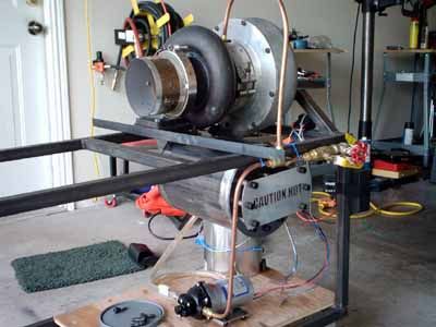
Ok, so you've made it this far. All you need now is a stand on which to mount your engine. You can see the test stand I made in other pictures here and get an idea of how to make one for yourself. Do you have your leaf blower ready? Ok, lets get it started!
Step 10: Have Fun Making Lots of Noise and Shaking the Ground While Impressing Friends and Neighbors With Your New Toy!

This is the fun part! Starting your new engine for the first time. The parts you will need are...
1) The engine
2) Ear defenders (ear muffs)
3) Lots of fuel (diesel, kerosine, or jet-a)
4) A leaf blower
5) a washcloth
This is where things get interesting. Firstly you set up the jet in a place where you can actually start it without making anybody mad with the loud noise. Then you fuel it up with your choice of fuel. I like to use jet-a because it just works well and has the right "smell" of a jet engine. Switch on your oil system and set the oil pressure to a minimum of 30 psi. Put on your ear defenders and spool up the turbine by blowing air through the engine with the leaf blower. Yes, you can use electric or air starting on these engines, but it is not the norm, and it is much easier to just use the leaf blower. Turn on the ignition circuit and slowly apply the fuel by closing the bypass needle valve on the fuel system until you hear a "pop" when the combustor lights. Keep increasing the fuel and you will start to hear the roar of your new jet engine. Gradually pull the leaf blower away and see if the engine speeds up on its own. If it does not, reapply the leaf blower and give it more fuel until it does. Lastly enjoy the sound of your new engine and remember to use the washcloth to clean up in case you poo your pants! There is so much power in these engines that it will startle you to the point of losing bodily control.
Videos of our running engines are available as flash movies below. We hope you enjoy them! You will probably need to size your browser down when viewing them so they are not pixelated.
That is about it. Our websites cover all of the build processes and hopefully will get you started on the journey of making your very own jet engine. Be sure to send us pictures if you make your own.
Combustor kits can be purchased by contacting Russ at Bad Brothers Racing. Different kits and configurations are available to help you in creating your jet engine. Fully assembled engines are also available to qualified buyers who sign a release of liability. The plans in this documentation and kit designs are Copyright 2006 Bad Brothers Racing, and may not be reproduced in any way, nor may they be sold.
Please remember that our websites are funded by donations and clicks on advertisements. If you feel generous, please help out with a monetary donation. If you are cheap, give us a few "clicks for the cause" to help the projects keep coming! See you soon, and we hope that you enjoy the sites!
This information was provided by Bad Brothers Racing and Gary's Jet Journal. Please visit our sites to see what is new as we update often with new and exciting projects.
http://www.badbros.net
http://www.garysjetjournal.com
First Prize in the
The Instructables Book Contest


