

Introduction: How to Control "stuff" From Your PC


Yes, but we manage hundreds of clients, and on different versions since 25 years, sometimes we get simple questions, but also we get critical production issues, all logged in different issue-tracking systems! so which issue to pick later? which one to pick now? and who is looking into it? did we notice it early enough?
Excuse me for the long introduction, it is just to tell you how I got this instructable idea, I wanted to build a simple and generic interface that can be used by any team/product management unit in the company to visually escalate client-raised issues, using warning rotary lights for example, put in the open space, so everybody can see the issue as it is being raised and thus act accordingly. At the end, somebody will assign oneself to the case, thus, the light goes off automatically.
...and it worked, for some reason I still don't understand, my colleagues are enjoying assigning themselves to raised issues! what an irony! maybe not for long, maybe not, I will see... :)
This project turned out to be useful also to do and control other stuff, so I made it as generic as possible, and here I am, sharing it with you, hope you will find it useful!
Basically, I built a simple interface that can control up to 8 AC devices (MAX 220 VAC, 2 Amp per output), along with 2 servo motors, using your PC, over USB. It is your call on how and where to use it, maybe some home automation, at work, or just for the fun of building!
Here is a quick video, sorry for the shaky camera, I just took it late at night hours before heading to work!
Let me know if you have any questions or comments.
f.
Step 1: General Design

I need to be able to use my PC to control a switch that will turn on/off a light.
In fact I want to control many lights, and even servos to move things around, so I though of using an Arduino board connected to my PC over USB, depending on specific commands I send to the board, the latter will switch specific outputs on/off, or move specific servos to a certain angle.
Sending commands from PC can be done directly from the Arduino IDE or by writing a software in any language that supports serial communication. The latter option provide flexibility to design a specific application, which I did for the office project, but for this Instructable we will be using the Arduino IDE to test the interface, and I let you explore building a specific application for your own uses (in any case, I used Java to write the logic and control application, let me know if you have a question in this regards)
Material needed:
1- Arduino board, I used the Nano
2- Sainsmart 8 Channel 5V Solid State Relay (SSR) Module Board. This is a great cheap and easy to use board, allowing isolated digital switching of 8 SSR relays using a 5 DC, 160 mA source when all channels ON (download schematic)
3- Electric wiring box (10 ports are enough)
4- USB cable mini
5- Power cable
6- 2 Servo extension chords
7- 8 electric sockets
8- 2 Servo motors, the specs (torque and speed) depends on what you are going to use them for.
9- A set of warning lights, depending on your needs (this is what i got)
9- Some wires
Design:
Below is the overall design, instead of the warning lights you can put any AC load, given that each load never exceed 2 Amp MAX and operating at 220 VAC max:
Step 2: The Code and Basic Test

To be easily able to identify and control different output/loads on the board, I wrote a set of codes, based on plain integer numbers, each code will cause a given output to go ON/OFF, similarly for the servos, 2 ranges of codes are used to control 2 servos separately with 100 step movement to be able to move the servo from 0° till 180°
Examples:
- Sending the code 11 will set light 1 to ON, sending 10, will turn it OFF
- Sending the code 200 will move the servo to 0°, sending 250 will move the servo to ~90°
- Sending 1000 will return back list of all Alarms defined in Arduino and their assigned pin, separated by a semicolon;
This logic applies to the all outputs, below is the mapping table of all codes:
Just download the Arudino IDE, I am using version 1.5.4, then open the attached code in the IDE, verify and upload. Make sure to select the Nano board from the list of boards (Tools > board), also the correct COM port where the Nano is connected (Tools > port)
If all goes ok, test all outputs, now simply by connecting a 220 Ohm resistor to a Led, where the negative led leg goes to Arduino Grd pin while the positive goes to the output being tested. Alternatively, you can connect the SainSmart 8 SSR board to the Nano for a quick end-to-end test, follow the general design in step 1, you can use jumper wires to make your life easier in connecting the Nano to the SainSmart.
Open the Arduino IDE serial monitor (Tools> Serial monitor), make sure the selected baud rate is 9600, then type a command from the table, and check if you get corresponding results as expected. Pretty straight forward, no? :)
Attachments

Step 3: Making a Box and Connecting the Electronics

Box and sockets
Build any box that suites your needs, basically this is where you need to put all the electronics and isolate the 220 VAC away from hands. In my case and since the warning lights I got use AC adapters, so I got a standard 10-port electric box, in addition to 8 electrical sockets, then fixed the sockets at each port.
SSR board
For the wiring, all sockets need to be connected in parallel, and to reduce the wiring in the box, I ran one wire (blue) that will come from the AC mains ,through all sockets (I soldered them in place to have a secure connection), I then soldered a lose wire (brown) at the second lead at each socket, (this is where the SainSmart outputs will later connect), I then placed the SainSmart SSR board, and connected each socket's lose wire to one of the outputs of the SSR board.
Finally, I connect the power cable, one lead (no matter which one) to the wire that runs through all sockets (blue), and another lead to the wire running through all output ports on the SSR board (brown) (refer to Step 1 for connections layout), I also prepared the wiring to the Arduino (bottom): 
Warning: Make sure to secure and insulate all exposed wiring, and never connect power while working on the inside of the box.
Arduino and other cables
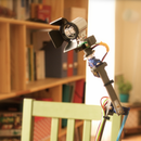
I fixed the Arduino Nano on the side of box and connected it to the SSR board as per the design in Step 1, then ran the USB and Servo cables out of the box, then connected 2 of the warning lights to ports 1 & 2 to test:
The servos, power and USB cables:
Step 4: The Box at Work
In the video, I am controlling the warning lights using the Java app I wrote, this application actually connect to a database, and once you hit Run, it scans the database for issues previously defined by users. When an issue is caught, the corresponding alarm is triggered, in our case, the warning light, Red or Blue depending on the issue type. It is part of the issue definition where you specify which light/port shall go ON/OFF..
Hope you will find better uses of this project, good luck!


