

Introduction: How to Make a Vacuum Powered Plywood Lifter for Your Workshop


I'm planning on building more than a few cabinets for an upcoming kitchen and bath remodel, on my house. I'll be using my 4x8 CNC router to cut the parts for the carcasses, out of 3/4 plywood. Shuffling 3/4 plywood around the shop has never been fun, its not that heavy but it is awkward for one person to move. So after looking at commercial solutions costing upwards of $2,000.00, I decided to build my own vacuum panel lifter, to bring plywood from a pile to my CNC router. My overhead track is 20' long. Lifting capacity is about 220 lbs (based on the P2950-EG 4 trolly capacity). The additional hose trolly keeps the air and vacuum hoses from getting tangled up
This would make a great setup to extend your wood shop fun to a ripe old age. I reckon I spent less than $450.00 to put this together.
Step 1: Materials Required


Materials required (your milage may vary):
Harbor Freight 2.5 cfm vacuum pump.
Wireless remote control electrical outlet, to turn the vacuum pump on and off.
2 Harbor Freight dual suction cup lifters.
4 20' coiled nylon air hoses.
15 feet or so 1/4" polyethylene tubing (for vacuum lines).
2 1/4 x 4 NPT pipe nipples.
9 1/8 NPT X 1/4 brass compression fittings.
For my hoist I used a Gardner Denver 1/2 ton air hoist, because I had it on hand. There is no reason an electric hoist couldn't be used.
Overhead Track and trolly: 4- 10' lengths of Unistrut or equal, I used Superstrut from Home Depot.
Trolly: 2- Unistrut P2950-EG 4 Wheel Trolley's, available from Amazon
Overhead hose trolly: 2- 10' lengths of 4" drain pipe, 1- 8" length of schedule 40 PVC pipe.
Various nuts bolts and screws.
Various 1/4" pipe fittings.
Step 2: Modify the Suction Cups


I started by taking the HF dual suction cups to pieces. Then I carefully scored the rubber on top of the cups with a razor knife and with a little additional cutting I was able to remove the inner metal disks. I drilled and tapped the disks for 1/8 pipe and screwed a 1/8 NTP x 1/4" compression fitting into the disk, as to be flush with the bottom of the disk (any excess can be filed off later) I added a little solder at each joint to secure it to the disk. I then glued the disks back into the rubber cups using Loctite Vinyl, Fabric & Plastic adhesive, being careful to make sure everything lined up in the process. I wound up clamping the rubber just to be sure I had good adhesion. Drill 3/4" holes in the plastic body of the lifters to accommodate the vacuum lines. I glued some 1" wood dowels inside the handles of the suction cups with epoxy resin to reinforce them. Then I assembled the cups while discarding the plastic levers.
I initially tried using rubber cement do glue the disks back together, but something went wrong with my ability to wait for it to dry before putting together.
These suction cups are not able to lift plywood without doing the mods and using a vacuum pump, They are capable of lifting non porous materials, such as glass.
Step 3: Putting the Lifter Together.


I built a vacuum manifold out of 3/4" schedule 40 pvc, by drilling and tapping for 1/8 pipe, then capping the ends. The suction cups and manifold are attached to a 2' length of Unistrut. The suction cup handles can be attached with 1.25" conduit Unistrut clamps., I made the mistake of getting 1.25 pipe clamps that were too big. I used some Unistrut parts I had laying around to make an eye for the lifter but a regular 1/2" eye bolt could be used instead.
Step 4: The Overhead Trolly


I have a truss roof in my workshop and I did not want to drill into the chords. so I welded some 1/2 x 6" bolts to the top of the lower piece (track) of strut and ran another length of strut on top of the lower chord and basically sandwiched the lower chords in between. then I ran a few 2x4 braces from the top chord down to the lower chord. I spot welded the track together where the 2 pieces met. The trolly body is made up of a couple of pieces of scrap aluminum channel bolted to either side of the 2 Unistrut wheeled trolleys. With the middle bolt going through the eye of the hoist.
I initially was a little over enthusiastic with my welding and had to spend an extra hour or so unwarping the sidewall of the strut where I joined them together.
Step 5: The Overhead Hose Trolly


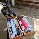
I needed some way to contain the vacuum hose for the lifter and the air hose for the hoist. So I slit two 10' lengths of 4" drainpipe on my table saw and using a short piece of 3" schedule 40 pipe as the trolly. I used two 20' foot lengths on either side of the hose trolly, as the hoses have trouble stretching to 20', the vacuum pump is on one end and the compressed air for the hoist is on the other. then a couple of 1/4" pipe nipples hold the air trolly in the track and supply vacuum and air to the lifter / hoist assembly. The green cable in the picture is necessary to drag the trolly from a parallel direction. The drainpipe is secured to the lower chords by wood screws with fender washers. I used a wireless remote control electrical outlet to turn the vacuum pump on and off.

Runner Up in the
Unusual Uses Challenge

Participated in the
Metal Contest


