

Introduction: How to Make an Arduino From Scratch


Frugal Engineering is the best way forward for science.
If you're interested in making some arduino's from scratch , you've come to the right place.
You can see a video tutorial of this instructable : here
It will supplement any loopholes or doubts you may have.
Lets start with an introduction on what we'll do in the next step.
Step 1: How Well Could It Be...if I Got an Arduino for Free..

INTRODUCTION : Question what to make,how to make,but make you must ...
After scrolling,searching,drooling over tons of Arduino tutorials..from making an led cube, to automating your home, giving life to a robot or making arduino powered drones... you, like me, must have felt that sudden urge as soon as you stumble upon an inspiring arduino tutorial,
"Gosh,Wish I had one of these" or better still "I want to make one of these, Right Now!" and as soon as that feeling hits your head, your eyes start scurrying the required parts list and you see that name :
ARDUINO : 25 Dollars and the cost of your project seems to skyrocket in many cases if other electronics are not as pricey( Yup, 25 dollars might be next to nothing for some, but yeah it is something!) and of course if the other parts are pricey,you need to burn a hole in your pocket anyway...Kachang!
And what's more heartbreaking(Believe me, its true!) is if you already own an Arduino, and its already the heart of your super Awesome robot(or Whatever) project.It's then when you start thinking - I don't want to dismantle my project apart.I don't want to invest my arduino in a project that i don't know will work or trying to make it work and that's when you decide ..well..yeah..I'll definitely make this new project ... but Later..not now...might as well bookmark it for now...WAIT! Stop ! No more will you have this for an excuse.We'll be minting an arduino right here,right now,so grab the parts in step 2 of this instructable,sit tight,grab your coffee and lets get to it .
Step 2: Get These Quick!

You require these starting materials:
Breadboard
AtMega 328 IC (you can use any variant like 328 PU or 328 P-PU )
Connecting wires,
Arduino(using an Duemilanove here),
1x 16 Mhz crystal,
3x 100 ohm resistors
1x 10K resistor
2x 22pF capacitors
3x LED's(A red ,yellow led and a green one)
1x 9v battery with connector snap,
1x usb cable,
1x 7805 Voltage Regulator
A computer or a laptop with arduino ide installed,
some free time and will to make things work
That's it..Lets begin tinkering...
Step 3: Beginning the Assembly


Grab your breadboard.It should look like the one in the picture perforated with lot of holes.
Put the AtMega chip (one that looks like a centipede) right down the middle of the board,
but keeping it closer to any one of the ends.
Step 4: Setting Up the Power Supply


Place the LM7805 voltage regular on the breadboard along with the ATMega 328 chip.
The pin placement of 7805 with the bulged side facing you is :Pin 1 - VCC, Pin 2 -Gnd, Pin 3 - Output.
Connect a black wire to pin 2 of the 7805 .Connect the other end of wire to the gnd rail on the breadboard.
Similarly connect a red wire to pin 3 of the 7805 whose other end will go to the vcc rail on the breadboard.
Connect a black wire to the ground rail which we'll connect with the ground of our Arduino(later).
To Connect the vcc and gnd rails along both the ends of the breadboard,connect 2 wires
as shown in the last few figures.
Step 5: Providing Power to the Chip


Take a good look at the At-mega to Arduino pin mapping given .
We're going to wire the circuit following it, so taking a look at it before prototyping will come in handy.
Particularly see the Vcc(+5V) and ground pin locations.
Connect red wires to pins 7 and 20 of the chip to 5V rail on breadboard.
Connect black wires to pins 8 and 22 of the chip to Gnd rail on breadboard.
Step 6: Making the Clockwork..


Add a 22pF capacitor between the Ground and pin 9 on the Atmega328 IC.
Add another 22pF capacitor between pin 10 of Atmega328 IC and ground.
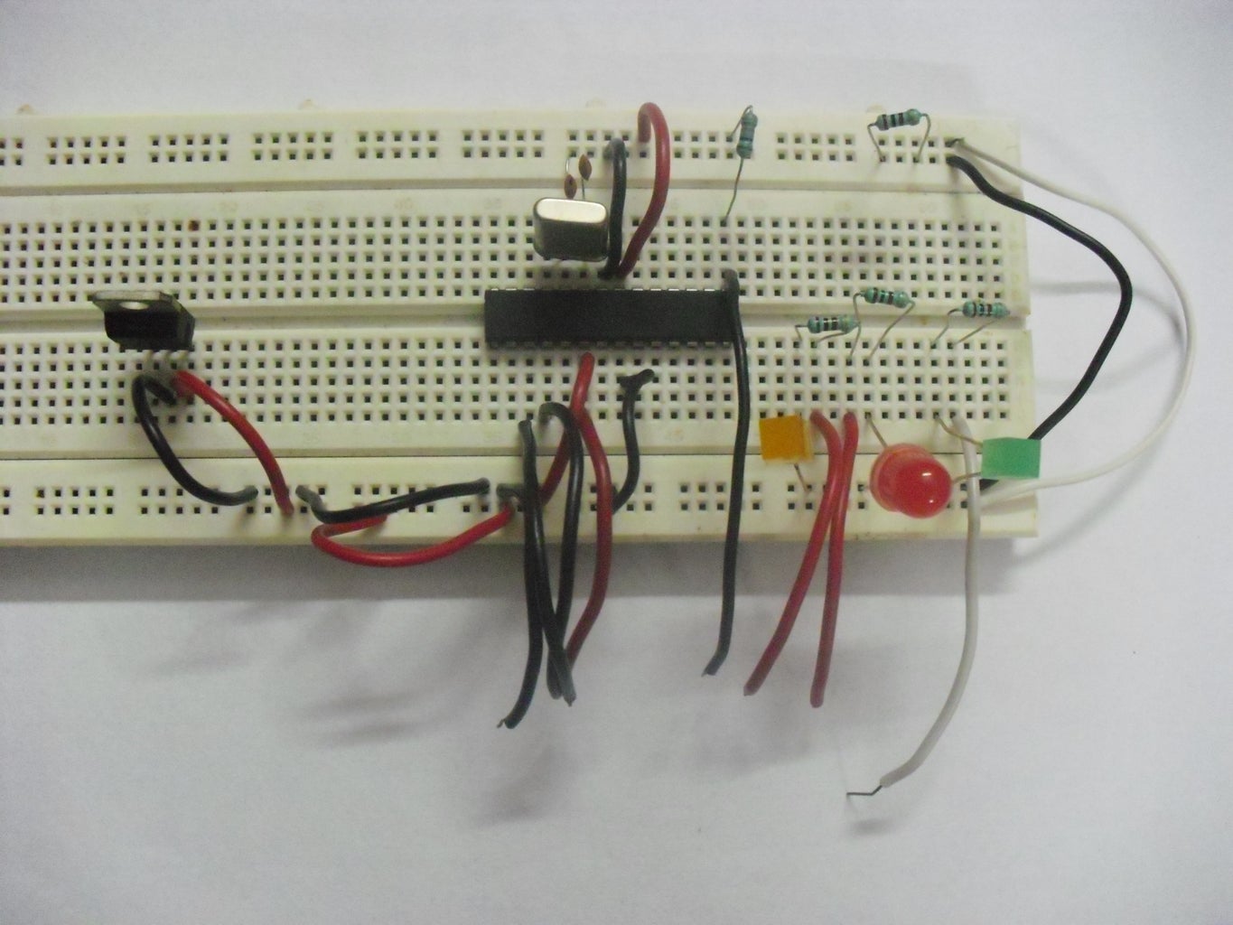
Finally add a 16 Mhz crystal between pins 9 and 10 on the Atmega328.
Add a 10k ohm resistor between the 5V and reset(pin1) of the 328 IC.
Your setup should now look similar to figure 4,5 of this step.
Step 7: Adding in the Status LED's


Add a wire on any one side of breadboard.
Connect a 100 ohm resistor to one of the ends where you connected the wire.(See pics).
Add the longer lead(+ve) of yellow led to the other end of resistor.
Connect the shorter leg(-ve) of the led to ground.
Do the above steps for red and green led's.
Step 8: Connecting Everyting With the Arduino


You're almost there!
Connect the yellow led wire to pin 9 of the arduino.
This functions as "Heartbeat". It shows the programmer is running.
Connect the red led wire to pin 8 of the arduino.
This functions as "Error indicator". It lights up if anything goes wrong.
Connect the green led wire to pin 7 of the arduino.
This functions as "Programming in Progress". It shows the programmer(Ardiuno) is in communication with the slave(ATMega 328 on breadboard).
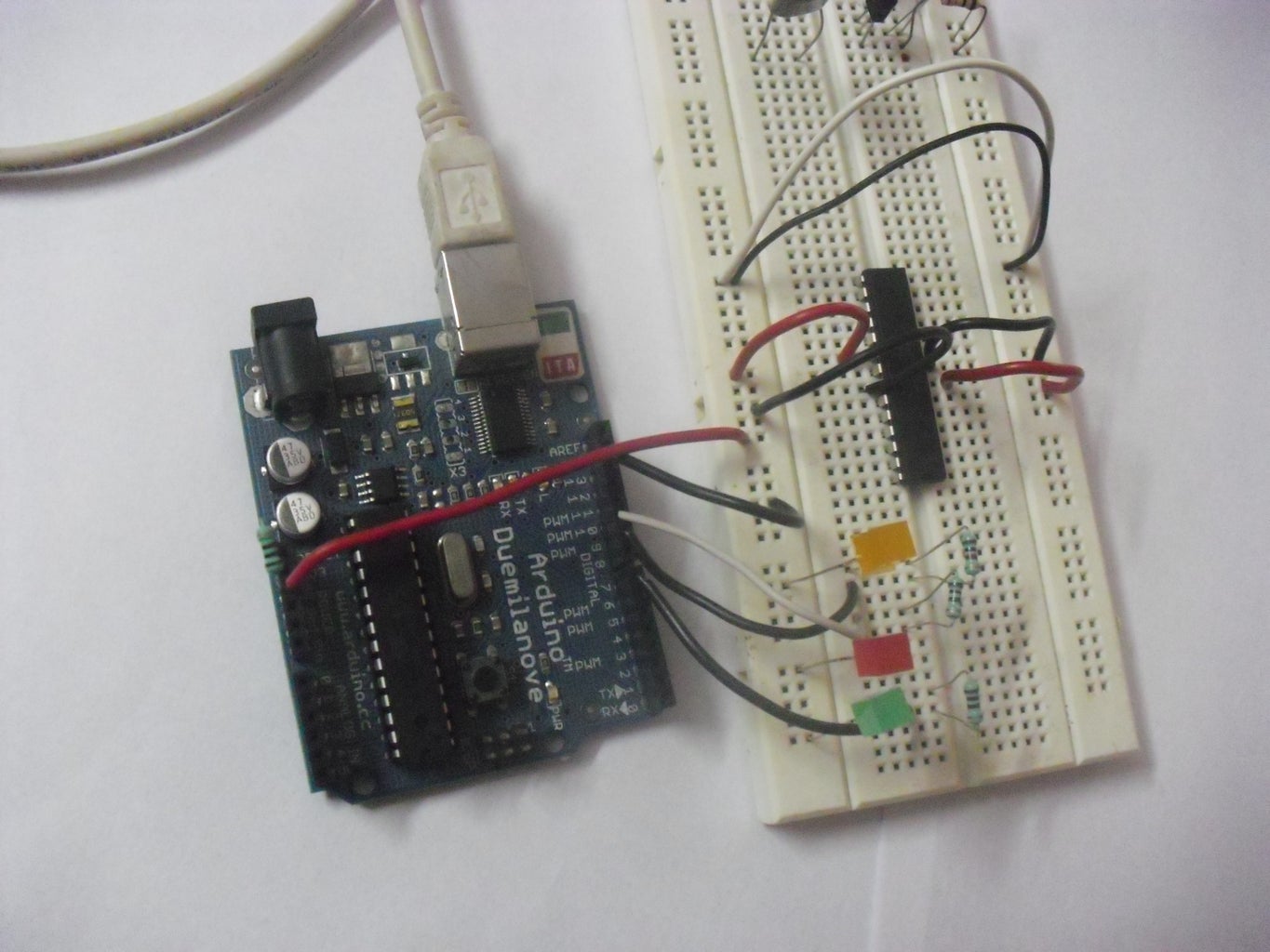
Connect 4 wires(3yellow and a green one) to pins on the Atmega IC on the breadboard
according to the pictorial schematic above..and connect them to pins 10,11,12,13on the arduino.
Also don't forget to attach the +5V and ground wires between the Arduino board and the breadboard.
Step 9: Programming Your Arduino
Let me tell what were going to do here.We're going to make your arduino basically burn the bootloader
onto the new Atmega 328 chip on the breadboard.
How? You may Ask.
Well, we'll be burning a program into our arduino to make it behave like a programmer!
1) Start the Arduino IDE.
2) Go to File > Examples > Arduino ISP.
3) Compile the sketch and burn it into your Arduino.
After you've burned the sketch,you'll see that the yellow LED will start to pulsate.
If it doesn't,check your connections again.Don't proceed further until you get this to work.
Now add a 100 ohm resistance between the 5V and the reset pin on the Arduino.
This is to disable the auto-rest which occurs on the Arduino.
Step 10: Setting Up the Burning...and Rise of an Arduino


In the Arduino IDE, select
Tools > Board > Arduino Duemilanove with AtMega328.
Programmer > Arduino as ISP.
Go to the tools menu and finally select the "Burn Bootloader" option.
Arduino IDE should now read : Burning bootloader, and if all went well the green led should come on.
The Tx and Rx pins on the Arduino should start flashing.
This process of burning the bootloader will take about a minute to complete.
Arduino IDE should now read : Done Burning bootloader
If it does,work done,Congrats,you now have a new Arduino chip.
If you had an Error, the RED led should come up.But don't fret.
Match your error type with the debugging guide in the coming steps.
Step 11: Troubleshooting Guide


See the pics of this step and Eliminate your problem.
Remember that you may have multiple errors and after you solve one error ,you may tumble into the next one.
But just follow the solution corresponding to the error and you'll be up and running in no time.
If you liked this tutorial or are having problems,post comments below.
Cheers and Happy building.

Participated in the
Tech Contest

Participated in the
Teach It! Contest Sponsored by Dremel

Participated in the
Microcontroller Contest


