

Introduction: How to Program Arcs and Linear Movement in G-Code Manually

Introduction
G-code is used in a lot of automated manufacturing processes. For example, CNC machines and 3D printers use G-code to make parts. Programming arcs and linear movement in G-code can be a little tricky. I've noticed that there aren't many sources on the internet that address this topic. So, I decided to make my own guide. I will be presenting basics steps and tips in programming arcs and linear movement in G-code. This will only include movement on a 2D plane and is designed to give a general overview of programming. The instructable will not take into account material properties, tool diameter, speeds, and feeds. I do encourage you to do all the calculations yourself as you go through my instructable. This will give you a better understanding of the code and remember a tool can become a crutch. Don't forget to use the tool path dimenisions .pdf as a reference.
Materials
- Paper
- Writing Utensil
- Scientific Calculator
- .pdf file of supplied technical drawing
-Time-approximately 60 min
Terminology
Absolute- A series of numerical positions that are calculated from a fixed point of origin.
Clearance Plane- A plane designated for safe tool travel in between cutting functions.
End point-The point where an arc ends
F variable- Feed rate (inches per minute)
G00- Rapid linear movement
G01- Linear interpolation
G02- Clockwise circular interpolation
G03- Counter Clockwise circular interpolation
I variable- Incremental coordinate used to define a point in the X direction.
Incremental- A series of numerical positions that is referenced from a previous position and is independent of absolute origin.
IPM-A unit of velocity used to determine feed rate. (inches per minute)
J variable- Incremental coordinate used to define a coordinate in the Y direction.
Origin- The fixed, central point in the Cartesian coordinate system. The origin has a numerical value of zero.
Start point- The point where an arc begins.
X variable- Absolute coordinate used to define a point in the X direction.
Y variable- Absolute coordinate used to define a point in the Y direction.
Formulas
1) Xs=Xc+(R*cos(Theta1))
2) Ys=Yc+(R*sin(Theta1))
3) Xe=Xc+(R*cos(Theta2))
4) Ye=Yc+(R*sin(Theta2))
5) I=(Xc-(R*cos(Theta1)))-Xc
6) J=(Yc-(R*sin(Theta1)))-Yc
Attachments

Step 1: Program Requirements
Before we begin, I will be designating a few requirements for the program. All units are in United States customary units. Z=0 will be the top face of the part. A clearance plane of .5000" will be used and a feed rate of 20 IPM. A depth cut of .1250" will also be needed.
The next few slides will be addressing the general structure of g-code commands we'll be using.
Step 2: G00 Structure
G00 commands the machine to move to a designated position at maximum feed rate.
GeneralStructure
G00 X#.#### Y#.#### Z#.####
Step 3: G01 Structure
G01 commands the machine to move at a specific feed rate to a designated position.
General Structure
G01 X#.#### Y#.#### Z.#.#### F#.####
Step 4: G02 and G03 Structure
G02 commands the machine to move in a clockwise direction to a designated point at a specific feed rate.
General Structure
G02 X#.#### Y#.#### I#.#### J#.#### F#.####
G03 commands the machine to move in a counter clockwise direction to a designated point at a specified feed rate.
General Structure
G03 X#.#### Y#.#### I#.#### J#.#### F#.####
Note
I and J define the location of the center of rotation --- RELATIVE TO THE CURRENT (STARTING) POINT
X and Y are the end point coordinates of the arc.
Step 5: Designating the Origin

The very first thing you should do is designate your part origin. The origin is the point where all absolute coordinates are referenced from. I will be using the center of the part as the origin.
Step 6: Designate and Order Points

Points are defined as places where a change in translation occurs. For example, a point would be where an x direction movement changes to a y direction movement or the start and endpoints of an arc. In the part I'm presenting, there are a total of 22 points. Each point has a unique set of coordinates that will translate into movement via g-code. Ordering the points will ultimately determine the structure of your program. For this example, I'll be initiating my cut at point 1 and continue in a clockwise direction around the part.
Step 7: Designate Arc Centers
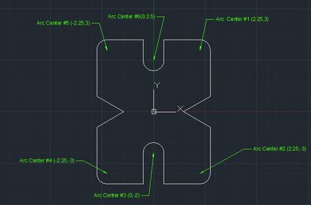
Finding the arc centers can be derived from the the technical drawing I supplied. There are a total of 6 arcs in the part. The arc centers are essential for finding the start and end points of the arcs, and the I and J variables.
Step 8: Calculating Start and End Points of Arcs
Calculating start and end points of arcs can be accomplished by designating the coordinates for the center point of the arc. Using the formulas I have supplied, just plug in the corresponding values for the variables. I encourage you to go through these calculations yourself. This will help understand the concept.
Defining Variables
R=Radius of arc
Theta1=angle of the position of the start point relative to the X axis
Theta2=angle of the position of the end point relative to the X axis
Xc=X coordinate of arc center
Yc=Y coordinate of the arc center
Xs=X coordinate of arc start point
Ys=Y coordinate of arc start point
Xe=X coordinate of arc end point
Ye=Y coordinate of arc end point
I=Incremental X coordinate of start point
J=Incremental Y coordinate of start point
Formulas
1) Xs=Xc+(R*cos(Theta1))
2) Ys=Yc+(R*sin(Theta1))
3) Xe=Xc+(R*cos(Theta2))
4) Ye=Yc+(R*sin(Theta2))
5) I=(Xc-(R*cos(Theta1)))-Xc
6) J=(Yc-(R*sin(Theta1)))-Yc
Step 9: Calculating Values for Arc 1

To calculate the needed arc values, just plug the numbers into the formulas for the respective variables. These values will be needed later to be input into the code.
Defining Variables
R=Radius of arc = .5
Theta1=angle of the position of the start point relative to the X axis = 90
Theta2=angle of the position of the end point relative to the X axis = 0
Xc=X coordinate of arc center = 2.25
Yc=Y coordinate of the arc center = 3
Formulas
1) Xs=Xc+(R*cos(Theta1)) = 2.25
2) Ys=Yc+(R*sin(Theta1)) = 3.5
3) Xe=Xc+(R*cos(Theta2)) = 2.75
4) Ye=Yc+(R*sin(Theta2)) = 3
5) I=(Xc-(R*cos(Theta1)))-Xc = 0
6) J=(Yc-(R*sin(Theta1)))-Yc = -.5
Step 10: Calculating Values for Arc 2

To calculate the needed arc values, just plug the numbers into the formulas for the respective variables. These values will be needed later to be input into the code.
Defining Variables
R=Radius of arc = .5
Theta1=angle of the position of the start point relative to the X axis = 0
Theta2=angle of the position of the end point relative to the X axis = 270
Xc=X coordinate of arc center = 2.25
Yc=Y coordinate of the arc center = -3
Formulas
1) Xs=Xc+(R*cos(Theta1)) = 2.75
2) Ys=Yc+(R*sin(Theta1)) = -3
3) Xe=Xc+(R*cos(Theta2)) = 2.25
4) Ye=Yc+(R*sin(Theta2)) = -3.5
5) I=(Xc-(R*cos(Theta1)))-Xc = -.5
6) J=(Yc-(R*sin(Theta1)))-Yc =0
Step 11: Calculating Values for Arc 3

To calculate the needed arc values, just plug the numbers into the formulas for the respective variables. These values will be needed later to be input into the code.
Defining Variables
R=Radius of arc = .5
Theta1=angle of the position of the start point relative to the X axis = 0
Theta2=angle of the position of the end point relative to the X axis = 180
Xc=X coordinate of arc center = 0
Yc=Y coordinate of the arc center = -2
Formulas
1) Xs=Xc+(R*cos(Theta1)) = .5
2) Ys=Yc+(R*sin(Theta1)) = -2
3) Xe=Xc+(R*cos(Theta2)) = -.5
4) Ye=Yc+(R*sin(Theta2)) = -2
5) I=(Xc-(R*cos(Theta1)))-Xc = -.5
6) J=(Yc-(R*sin(Theta1)))-Yc = 0
Step 12: Calculating Values for Arc 4

To calculate the needed arc values, just plug the numbers into the formulas for the respective variables. These values will be needed later to be input into the code.
Defining Variables
R=Radius of arc = .5
Theta1=angle of the position of the start point relative to the X axis = 270
Theta2=angle of the position of the end point relative to the X axis = 180
Xc=X coordinate of arc center = -2.25
Yc=Y coordinate of the arc center = -3
Formulas
1) Xs=Xc+(R*cos(Theta1)) = -2.25
2) Ys=Yc+(R*sin(Theta1)) = -3.5
3) Xe=Xc+(R*cos(Theta2)) = -2.75
4) Ye=Yc+(R*sin(Theta2)) = -3
5) I=(Xc-(R*cos(Theta1)))-Xc = 0
6) J=(Yc-(R*sin(Theta1)))-Yc = .5
Step 13: Calculating Values for Arc 5

To calculate the needed arc values, just plug the numbers into the formulas for the respective variables. These values will be needed later to be input into the code.
Defining Variables
R=Radius of arc = .5
Theta1=angle of the position of the start point relative to the X axis = 180
Theta2=angle of the position of the end point relative to the X axis = 90
Xc=X coordinate of arc center = -2.25
Yc=Y coordinate of the arc center = 3
Formulas
1) Xs=Xc+(R*cos(Theta1)) = -2.75
2) Ys=Yc+(R*sin(Theta1)) = 3
3) Xe=Xc+(R*cos(Theta2)) = -2.25
4) Ye=Yc+(R*sin(Theta2)) = 3.5
5) I=(Xc-(R*cos(Theta1)))-Xc = .5
6) J=(Yc-(R*sin(Theta1)))-Yc = 0
Step 14: Calculating Values for Arc 6

To calculate the needed arc values, just plug the numbers into the formulas for the respective variables. These values will be needed later to be input into the code.
Defining Variables
R=Radius of arc = .5
Theta1=angle of the position of the start point relative to the X axis = 180
Theta2=angle of the position of the end point relative to the X axis = 0
Xc=X coordinate of arc center = 0
Yc=Y coordinate of the arc center = 2.5
Formulas
1) Xs=Xc+(R*cos(Theta1)) = -.5
2) Ys=Yc+(R*sin(Theta1)) = 2.5
3) Xe=Xc+(R*cos(Theta2)) = .5
4) Ye=Yc+(R*sin(Theta2)) = 2.5
5) I=(Xc-(R*cos(Theta1)))-Xc = .5
6) J=(Yc-(R*sin(Theta1)))-Yc =0
Step 15: Assign Coordinates to Each Point

An easy way to do this would to recreate your intended part in a CAD system. This method would allow the computer to make all the calculations. If you are doing this by hand just assign your calculated values to the points on the arc. The coordinates of straight lines can be derived from the technical drawing I supplied. An easy way to keep track of all your coordinates and points is to keep a table of all the points.
Step 16: Beginning the Program
So, in order to program this part you have to think of where the initiating cut will be and which direction the tool will be moving. In this case, we will initiate the cut at point 1 and continue around the perimeter of the part in a clockwise direction. The last command used should bring you back to the start point.
Step 17: Moving to Point 1

So for the Initiating cut, we need to tell the machine to go to point 1 at the designated clearance plane of .5000" above the top face of the part. To do this we will need to use a G00 command to move to the required coordinate.
This is what the first line should look like
(I will continue to add lines of code to the first line to help guide you)
G00 X.5 Y3.5 Z.5
(At this point there is no cutting happening as the tool is still .5000" above the part)
Step 18: Moving to Cut Depth
Now that were are centered at point 1, we need to feed down to .1250" below the top of the face, to the cut depth. Since the tool is already at point 1, only a Z variable will need to be defined using the G01 command at 20 IPM.
Now the code should look like this
G00 X.5 Y3.5 Z.5
G01 Z-.1250 F20
Step 19: Moving to Point 2

Now the tool needs to move to Point 2. Since Point 1 and 2 are at the same Y value only an X value will be needed to command a horizontal move.
Now the code should look like this
G00 X.5 Y3.5 Z.5
G01 Z-.1250 F20
X2.25
Step 20: Moving to Point 3 Along Arc 1

This is the first arc. Since this the tool will sweep along the arc in a clockwise direction, a G02 command will need to be used. This arc will only take one line of code. Just plug in the numbers that you calculated for arc one.
(Remember the X and Y coordinates of an arc command is the end point of the arc. Plug in the calculated I and J values for Arc 1)
Now the code should look like this
G00 X.5 Y3.5 Z.5
G01 Z-.1250 F20
X2.25
G02 X2.75 Y3 I0 J-.5
Step 21: Moving to Point 4

Since this is linear movement a G01 command will need to be inserted in the next line of the code along with the new Y coordinate.
Now the code should look like this
G00 X.5 Y3.5 Z.5
G01 Z-.1250 F20
X2.25
G02 X2.75 Y3 I0 J-.5
G01 Y.75
Step 22: Moving to Point 5

The path from point 4 to point 5 is a diagonal path, but is still linear so it can be still defined with a G01. With a diagonal line an X coordinate and Y coordinate need to be defined.
Now the code should look like this
G00 X.5 Y3.5 Z.5
G01 Z-.1250 F20
X2.25
G02 X2.75 Y3 I0 J-.5
G01 Y.75
X1.451 Y 0
Step 23: Moving to Point 6

The path from point 5 to point 6 is another diagonal move, so an X variable and Y variable will need to be defined.
Now the code should look like this
G00 X.5 Y3.5 Z.5
G01 Z-.1250 F20
X2.25
G02 X2.75 Y3 I0 J-.5
G01 Y.75
X1.451 Y 0
X2.75 Y-.75
Step 24: Moving to Point 7
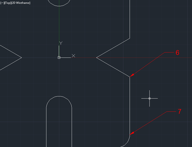
This is a linear move down along the Y axis. It can still be defined under the G01 command.
Now the code should look like this
G00 X.5 Y3.5 Z.5
G01 Z-.1250 F20
X2.25
G02 X2.75 Y3 I0 J-.5
G01 Y.75
X1.451 Y 0
X2.75 Y-.75
Y-3
Step 25: Move to Point 8 Along Arc 2
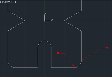
Arc 2 is another clockwise arc so a G02 command will need to be used.This arc will only take one line of code. Just plug in the numbers that you calculated for Arc 2.
(Remember the X and Y coordinates of an arc command is the end point of the arc. Plug in the calculated I and J values for Arc 2)
Now the code should look like this
G00 X.5 Y3.5 Z.5
G01 Z-.1250 F20
X2.25
G02 X2.75 Y3 I0 J-.5
G01 Y.75
X1.451 Y 0
X2.75 Y-.75
Y-3
G02 X2.25 Y-3.5 I-.5 J0
Step 26: Move to Point 9

The move to point 9 is a horizontal move in the X direction. A G01 command will need to be inserted into the code and an X variable will need to be defined.
Now the code should look like this
G00 X.5 Y3.5 Z.5
G01 Z-.1250 F20
X2.25
G02 X2.75 Y3 I0 J-.5
G01 Y.75
X1.451 Y 0
X2.75 Y-.75
Y-3
G02 X2.25 Y-3.5 I-.5 J0
G01 X.5
Step 27: Move to Point 10

The move to point 10 is vertical move along the Y axis. A Y variable will need to be defined on a new line under the current G01 command.
Now the code should look like this
G00 X.5 Y.3 Z.5
G01 Z-.1250 F20
X2.25
G02 X2.75 Y3 I0 J-.5
G01 Y.75
X1.451 Y 0
X2.75 Y-.75
Y-3
G02 X2.25 Y-3.5 I-.5 J0
G01 X.5
Y-2
Step 28: Move to Point 11 Along Arc 3

The move to point 11 is a counter clockwise move. A G03 command will need to be inserted into the code. Just plug in the numbers that you calculated for Arc 3.
(Remember the X and Y coordinates of an arc command is the end point of the arc. Plug in the calculated I and J values for arc 3)
Now the code should look like this
G00 X.5 Y3.5 Z.5
G01 Z-.1250 F20
X2.25
G02 X2.75 Y3 I0 J-.5
G01 Y.75
X1.451 Y 0
X2.75 Y-.75
Y-3
G02 X2.25 Y-3.5 I-.5 J0
G01 X.5
Y-2
G03 X-.5 Y-2 I-.5 J0
Step 29: Your Program Is Now Halfway Done!
This marks the half way point of the code. To finish the second half of the code, use the same techniques I presented in the previous steps. Before you move on to the next step, finish the second half of the code and compare your code to the master code. Remember, your last line of code should bring you back to point 1 to finish the cut.
Step 30: The Master Code
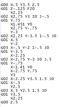
This is what the finished code should look like. I will also include a copy of my .txt file of the completed functional code for those of you using a CNC simulator.
Attachments

Step 31: Here's a Video Simulation
Step 32: Conclusion
Congratulations! You have created a G-code program. By completing this instructable, I hope it has given you some insight in programming. Programming arcs can be a little tough at first, but with practice it get's easier. Please feel free to leave any comments. Thank you for taking the time to use my instructable.


