

Introduction: Huge Arduino Animatronic LED Eyeball


I'm currently in the process of making a Halloween contraption that has a few components that are worth documenting. The Huge Arduino Animatronic LED Eyeball is one of them.
Background
Most animatronic eyeball projects that I found were more or less life-size. They were usually ping pong balls or dolls eyes or 3-D printed. I needed something bigger. I needed it to proportionally fit into a 2-ft diameter sphere. It didn't need it to be high fidelity, though it did need to look kind of cool (otherwise the kids would think it was lame). I wanted to keep open the ideas of a cyclops or a 2-eyed monster. It needed to be animated to appeal to kids. Illumination was optional. The project itself couldn't be expensive nor overly complicated. Finally, after Halloween was over, I wanted to be able to dismantle everything and reuse the parts for future projects.
Step 1: Parts


Eyeball
- Westinghouse 4in x 8in White Clip-On Shade (8149400), $3
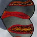
- Ladybug felt (1.5" black dots on red background)
- Spray on adhesive
Eyeball Backing
- Craftsman Universal Joint, 1/4 in. Drive, $8
- 270 ohm resistor, x3
- 5mm RGB LED, common anode, x5
- 4mm Coroplast, ~9" square
- Foam board, ~5" square, $1
- Various color wire, 26 awg
- TE Connectivity / AMP 640456-4
- TE Connectivity / AMP 36438154
- 10lb picture hook, x2
- Hot glue
- Electrical tape
Sensors
- HC-SR04 Ultrasonic sensors, x2, $3 ea
- Ethernet cable, ~4ft
- TE Connectivity / AMP 36438154, x4
- TE Connectivity / AMP 6404574, x2
- Electrical tape
Platform
- Simpson Strong-Tie tie plate TP37, $3
- Everbilt aluminum angle 1" x 36" x 1/16"
- Hex bolt 5/16" x 1" and nut, x3
- Bolt 1/4" or 5/16" x 1" or 1 1/2", x2; nut, x2; washer, x4
- 3/8" plywood, 8" x 6"
- 11/32" (dia) x .014" (thick) brass tube, $3
Movement
- TowardPro MG996R servo and arm, x2, $9 ea
- Music wire .047, $1 (can use a metal coat hanger)
- Large zip tie
- Heat shrink tube, large enough to fit over zip tie and servo arm, x2
- Cyanoacrylate (aka CA or Super Glue)
- Rainbow loom bands
Microcontroller
- Sparkfun RedBoard (their Arduino UNO clone), $9 on Arduino Day
- Half-size breadboard, $4
- Velcro with adhesive backing
- Jumper wires
Power
- battery packs, x2
There are only a few key items which make this project successful, IMHO. The first is the Westinghouse clip-on shade. It's the perfect size and shape, lightweight, translucent, hollow, and cheap. The second is the 1/4" socket wrench universal joint in conjunction with the 11/32" brass tube. I tried a RC universal joint but it way too floppy. The socket wrench universal joint has enough friction to create a tighter movement. It also has enough degrees of freedom for this project. The brass tube provides a very snug fit over the joint's male connector. Together they make a very nice rod and joint (more like tube and joint) system. The last item is the Coroplast. It is lightweight, rigid, and easy to cut. When cut perfectly to the inner dimension of the clip-on shade, it provides a very snug fit especially when pushed into the shade a bit. It won't rotate or accidentally fall out (at least it hasn't done so yet). And it can be popped in and out of the shade without it starting to fail. I originally had tried foam board but it started to bend and loose its rigidity. Thin plywood was my other choice, but it seemed to heavy.
As for the rest of the parts, use whatever works for you.
Step 2: The Eyeball

This is the simplest part of this project. Just cut out a circle of the ladybug fabric around a black dot. Get a large enough area for a nice red iris. Place it on the clip-on shade and shape it until you like it. Lastly, tack it down onto the clip-on shade. For a very long time, I just used double-stick tape because I wasn't committed to using the felt. I was thinking about possibly having blue or green eyes or even snake eyes. Once my daughter decided red was it, I attached it with spray on adhesive which doesn't create glue lines or hard spots in the felt.
Obviously you don't have to use ladybug fabric. That's just what I had laying around. You can use whatever you want - paper, paint, fabric, etc.
Step 3: The Eyeball Backing


Cutting the Backing Circle
With a very sharp pencil or fine tip pen trace the clip-on shade onto the Coroplast. Find the center of the circle just traced and mark it. Cut exactly on the trace line. Put the circle up against the shade. It will be too big fit inside. Now, ever so slightly, trim down the circle until it fits snugly into the shade. At some point it'll be very difficult to pop out. Use an Exacto knife to pry out the Coroplast. Trim down the circle to the point where the entire circle fits into the shade and can be pushed in a few millimeters or so.
Attaching the Universal Joint
Verify that the center you marked is still your center. Adjust if needed. Draw a vertical and horizontal line from the center point. Use the Coroplast ribs as one of your lines. Then make sure the other line is exactly perpendicular to it.
When attaching the universal joint to the Coroplast, the goal is to line up the joint's pivoting movement with the lines just drawn. Easiest way to do this is to put the universal joint face down on the center mark of the circle and pivot the other part of the joint up and down and then left and right making sure it looks true. Don't let the orientation of the joint's connector part guide you as they don't seem to be aligned to anything. Now create a reference mark on the joint and on the circle so it's easy to know how to place it down when gluing.
Use a liberal amount of hot glue on the joint and on the circle. Place the joint down on the circle matching up the reference mark. Quickly test the up, down, left, right movements to see if the alignment is true, rotating the joint if it isn't. Work fast, the hot glue dries quick!
After the glue fully dries, the brass rod can be attached so that it's easy to see how the eyeball will move.
Servo Push Rod Attachments
These are the things that the servo rod attaches to to move the eyeball around. I just used a J-style picture hook. Carefully straighten the top portion so that it looks like an L-bracket. Trim off the excess leaving some to be glued to the Coroplast.
To position them, align them on the axial lines that were previously drawn and about 1/2" from the edge. The distance from the edge was arbitrary. Do what works for you.
Illumination
RGB LEDs are used to light the eyeball. If they are clear lens LEDs, diffuse them. Wire them in a series since there will only ever be one color at any given time. Because each LED has 4 leads, mount them LEDs on a foam board and wire half of the leads on one side of the board and the other half on the other side of the board. This helps prevent short circuits in as small space. Create leads to the unit about 1.5 ft long. At the end of the leads attach a 4-wire connector. Then attach this connector to it. I have no idea if these connectors are meant for this purpose. They are convenient and they plug into a breadboard nicely. Finally, make a hole in the Coroplast and feed the LED wires through so that it sticks out the back.
Step 4: The Sensors
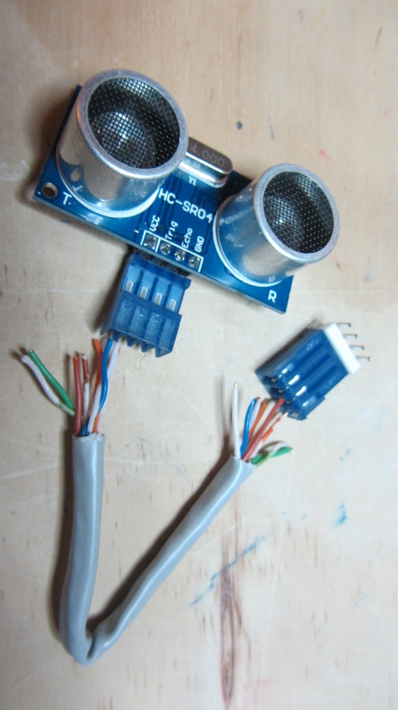
The ultrasonic sensors are used to detect objects on the left and right hand sides of the eyeball. Only the horizontal servo benefits from these sensors, but I thought I'd have the eye randomly look up or down when looking left or right to give it some character.
Basically all that this step is about is extending the pins on the ultrasonic sensor by 1.5ft to 2ft. Using the TE connectors make it easy to put on and take off the ultrasonic from the cable. Also, the connectors makes it easy to connect the cable on and off the breadboard. Lastly, using an Ethernet cable is nice because it has the sheath already keeping everything tidy. As always, use what works for you.
Step 5: Platform


It looks more complicated than it is. If built in this order, it should be problem free. The hardest part is making a hole in the tie plate for the servo.
Wooden Base
- Cut 8" x 6" of 3/8" plywood for base. Here I used cabinet plywood.
- Cut 2 3/8" x 1" plywood for shim
- Measure a hole for the horizontal servo 2" from the right and 3/4" from the eyeball side.
- Align shim center atop the base center and flush it against the eyeball side edge
- Hopefully the shim doesn't overlap the hole. If it does, either adjust the position of the shim, the hole or both.
- Mark the positions
- Measure twice and verify
- Cut the hole making sure the servo fits in the hole
- If you have to make the hole wider, grow the hole away from the center
- Put the servo into its hole
- Glue the shim down butting up next to the servo
- Don't get glue on servo
In my picture above, I cut a shim much bigger than I'm documenting. I had to chisel some of it away in order to fit the vertical servo bracket. The part with the "X" is not needed.
Eyeball Bracket
- Cut 2 3/8" of 1" x 1" right angle aluminum
- When sitting atop the shim, make sure that it doesn't block the servo hole
Eyeball Bracket on Base
- Drill 2 holes using 5/16" drill bit in one of the aluminum faces so that they are each 3/8" from the side and in the center
- Verify 5/16" bolts fit
- Put horizontal servo in its hole
- Clamp bracket onto shim and base
- Though the bolt holes, mark 2 centers in which to drill through the shim and base
- Drill out the two holes in the shim and base
- Verify 5/6" bolts fit bracket and shim and base
- Bolt the aluminum to the shim and base
Eyeball Bracket to Eyeball
- Find the center of the bracket face that'll attach to the eyeball
- Drill out a hole with a 5/16" drill bit
- Verify 5/16" bolt fits
- Attach nut to bolt and tighten down
Eyeball Bracket Tube
- Cut 1 3/8" of brass tube
- Verify that it fits over 5/16" bolt
- Hot glue the tube onto the bolt
Vertical Servo Bracket
- Measure 1 3/4" along the length of the tie plate
- Bend to 90 degrees
- Measure another 3 1/4"
- Bend to 90 degrees
- Measure 1 1/4"
- Cut off excess
- Cut the hole making sure the servo fits in the hole
When cutting the hole into the tie plate for the servo, I used a drill and then a scroll saw. After breaking 2 scroll saw blades, I tried a Dremel with cutting bits. It took two cutting bits to finish the hole. If you don't have the means to cut a tie plate, like I didn't, maybe build the bracket out of wood or Coroplast, aluminum, foam board or a metal Band-Aid can. The most important dimensions to maintain are the height of the bracket, 3 1/4", and possibly the effective distance of the servo from the front edge of the base, 1 3/4".
Step 6: Movement


There are 2 main parts to this section: getting the length of the servo arms correct and getting the length of the connecting rods correct.
Extending the Servo Arms
- Extend one arm of both servo arms so that from spline center to end is 1 3/4"
- Cut a length of zip tie. Try to use a zip tie whose width is large enough so that when attached to the servo arm it will not bend during use.
- Sand the top of the servo arm
- Sand the bottom of the zip tie
- Glue the zip tie atop the servo arm using CA
- Slide heat shrink tube over arm and zip tie and shrink
- Punch a hole at the end to fit the connecting rod
The goal is to extend the servo arm so that when a rod is connected to it and the eyeball backing plate, the rod meets the eyeball backing plate at a 90 degree angle or less. If it's greater, there's a potential for the edge of the eyeball to rotate (to the right) into the servo arm.
Creating the Connecting Rods
- For the vertical servo connecting rod, cut a length of rod an 1" or so longer than 5 3/4"
- Create a 1/4" L-bend at one end
- Bend the rod 5 3/4" from the L-bend to create another L-bend. Make the L-bends point in the same direction.
- Cut excess
- For the horizontal servo connecting rod, cut a length or rod an 1" or so longer than 4 5/8"
- Create a 1/4" L-bend at one end
- Bend the rod 4 5/8" from the L-bend to create another L-bend. This time it should point perpendicular to the first one.
- Cut excess
Step 7: Attaching and Mechanical Test


At this point, all the parts can be attached together to see how they fit. They eyeball can be rotated to see the range of motion. The servo arms can be moved to see if anythings restricts movement. If something doesn't quite work, it is easily adjustable.
- Remove the eyeball backing plate from the clip-on shade
- Attach the universal joint to the brass tube aligning the picture hooks at the 12 and 9 o'clock (looking from the backside) positions
- Put on the clip-on shade
- Attach the servo arms to the splines
- Attach the rods from the servo arms to the picture hook
Rotate the servo arms to get an idea of how the eyeball will move. Make any necessary adjustments. When all done use tiny rubber bands to hold the rods in their holes.
Step 8: Electronics

The final part of this project is wiring everything together and programming the movement. It's fairly simple with only a few things to remember. To keep the package somewhat neat, the breadboard and microcontroller are held down to the platform using sticky backed Velcro (I didn't show this in the video).
Wiring Together
Just follow the diagram. The servos will need their own power supply separate from the microcontroller's power supply. I used 7.4v LiPo's for both. Use what works for you.
Programming
Attached is the Arduino UNO code. It utilizes the NewPing library, which will have to be installed, and the Servo library, which should already be installed. Following the recommendation of the NewPing author, the code is event driven, meaning there are no delay() calls. This can be difficult to work with at times.
Attachments


Finalist in the
Sensors Contest

Participated in the
Battery Powered Contest

Participated in the
Glue Contest


