

Introduction: Hyper Terra


"Hyper Terra" is a projection-mapped sculpture with an integrated projector, computer, and power supply. The sculpture is a mountain with simulated solar and lunar lighting that can be set up with any lat/long on Earth and a point in time. The graphics software has controls for time advancement towards the past or future, the long/lat on Earth, solar/lunar positioning, light color, and more. The result is both a sculpture and a dynamic visual timepiece.
Artist and Author: Gabriel Labov Dunne (www)
Title: "Hyper Terra"
Instructable Link: https://www.instructables.com/id/Hyper-Terra/
Flickr Gallery: https://www.flickr.com/photos/quilime
Description: An abstract landscape is illuminated by light and shadow generated by sun and moon positions from any time and place on Earth. Graphics are projection-mapped onto the landscape by an embedded projector and computer, powered by an integrated power supply.
Medium: MDF, Birch Plywood, Aluminum, LCD Projector, Embedded Computer, Power Supply, Custom graphics software written in C++
Tooling: CNC, Water Jet, Laser Cutter, Wood Shop, Metal Shop
Design Software Used: McNeel Rhino/Grasshopper, Autodesk Inventor/HSM, Autodesk Maya
Step 1: Concept


To execute this concept, I began sketching ideas for dioramas and miniature scenes. I also had to include an embedded computer and projector to somewhere to augment the time and place of a scene. I started out with boxy-like diorama constructions and varied all the way to craggily peaks and towers.
In my research I was also interested in traditional Chinese model landscapes call 山水 盆景, or “Penjing”, which represent small landscape models and/or living sculptures. Sometimes these sculptures include practical effects such as real water, plants, smoke, and lighting. One thing I especially appreciated about these small landscapes is that you could view it from all angles. I felt this was extremely important, so I ditched any ideas that involved putting the project in a box.
Goals
- The projection should work decently when there is bright ambient light.
- The object should be viewable from all angles.
- The projection computer should have a fast start-up time, allowing the sculpture to be turn on and off quickly seamlessly.
- Software settings should be easily set an controlled from a tablet or phone, or other seamless interface.
Software Ideas
- Color gradient of the sky.
- Cloud layer and atmosphere, such as fog
- Color temperature (Kelvin) throughout the day.
- Colors and texture themes that could represent seasonal foliage, rain, and snow.
- A body of water so I can play with the aesthetics of specular reflections of the sun and the moon.
- Calendar events and cycles.Movement of the Earth the sun, the moon, and the stars, based on actual astrological positions, using and ephemeris table or pull from the internet.
- Night-time motifs. It would be cool to include tiny roads with car headlights, traversing through the mountains, or other urban lighting effects.
Because the software is ephemeral, and the sculpture is physical, it's easy to have many visual ideas before committing to them as I can upgrade the software at any time.
Step 2: Landscape Design


For my landscape, I created an object with Rhino/Grashopper. Vertices define the shape, and then I used the Delunay node in Grasshopper to generate the mesh.
I designed the form keeping in mind the amount of labor it would be to hand map each vertex later, which is basically projection mapping ground-zero. If other helpful mapping techniques aren't available (see OpenCV, Structured Light), one can always place vertices by hand. I created a shape with less than 100 points, so even if each vert took a minute (unlikely), at most it would take less than 2 hours. I planned to have the projector locked to the form, so I only have to do this mapping once.
I used this same landscape model my entire residency, it was interesting to see it evolve. I never had the chance or inspiration to design a new object, as this one just worked. They software works with any object, and the base is modular, so I can make new designs in the future and they can fit right in to the system.
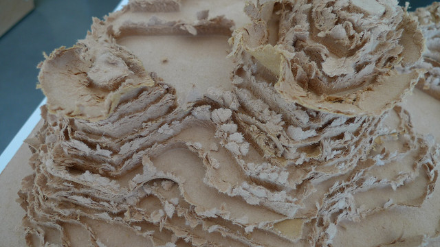
Step 3: 3D Printing Test Models


I 3D printed some mini models with a trusty MakerBot Duo for projection tests.
A really interesting thing happened with some old ABS plastic filament that had been sun-bleached and discolored, resulting in some landscape striations that resembled real stoned and sediment layers.
Step 4: Raspberry Pi Projection-Mapping Setup


I zip-tied a raspberry pi to a pico projector, and mounted the whole rig on a tripod. I created a simple mesh-mapping projection software with OpenFrameworks, and then projected upon the 3D printed objects.
A cool thing about the equipment setup is that I could power the RPi from the USB port on the projector, leaving me with only one power plug.
I also really liked how the semi-transparent PLA played with the light. It sometimes felt like the objects were illuminated from within.
This step about using the Raspberry Pi as a mini-mapping became its own Instructable: Mini Projection Mapped Sculpture.
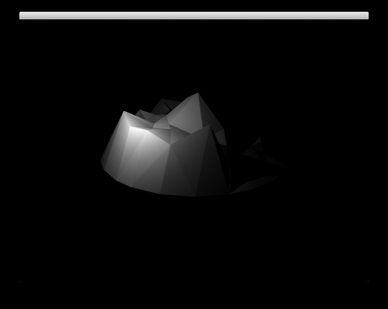
Software Screencap:
Mapping Result:
In this software, I simply had a virtual lights revolving around an object in sinusoidal patterns. There was no positioning based on the sun or the moon at this point.
As far as the projection quality, while I love the form factor of the little DLP pico projectors, I much prefer using LCD technology because it gives a much better image when documenting on video. I'm still searching for a bright, LCD-based pico projector with a small form factor. Due to crossover conversations I had with some otherawesomeAiR's at Pier 9, I see the potential mangling a consumer LCD projector to reduce the form factor, or potentially fabricate my own, all the way down to the lenses.
For an extreme example of how crazy DLP banding can get, to the point where it can be utterly psychedelic, check this out:
Step 5: Create Toolpaths for CNC MIlling


I had grown to like this little landscape and wanted it to be a little bit larger than the 3D printed tests, so I prepared the sculpture for milling.
I used Autodesk Inventor HSM to generate my tool paths for the 5-Axis DMS router at Pier9. As a material, MDF is great for testing, and ultimately I used it for my final piece as well.
Step 6: Stock Prep and Layup


I cut everything to the material bounds with the table saw, and then created Layer-cakes of MDF panels and wood glue to both sides so just a little bit seeps out the sides, clamp, and set to dry.
Step 7: Roughing Passes

The roughing passes took about 20 to 30 minutes.
Ridiculous amounts of dust.
The mountain is revealed.
Step 8: Clean Up Between Passes


It took a few tries to get my feeds and speeds right with the MDF layups. I was looking for the right combination of speed and chip size. Huge thanks to Dan, Pier 9 CNC Master Chief.
Sometimes, opening the doors of the DMS reveals a ridiculous pile of chips, resembling a fuzzed-out MD5 dust mountain. This is before we had the fancy dust-collection integrated into the DMS.
Cleaning up the chips and dust was felt like uncovering an archeological relic.
Since these photos were taken, I have definitely improved my CNC technique and I now pause the pass to clean up so I can see the tool head operating. These photos were among the first I took when learning the ins and outs of the DMS.
Step 9: Finishing Passes


Finishing passes were done with a 1/2" round bit and averaged 30 to 40 minutes.
Step 10: Milling Strategies


Overall, I milled a pretty wide array of scales and forms, the largest being 18" dia by 6" height out of MDF, to baby 4" diameter wax versions on an OtherMill.
I also had some interesting fails along the way. This is what happens to MDF with too fast of a tool feed rate.
Step 11: Separately-Milled Mountain Peaks


I had to work out a few tooling strategies in order to get the sharpest edges possible with the milling process. Some methods involved milling the mountain peaks separately so I could use shorter, finer bits in the finishing passes.
After milling, I had to clean them from the stock before attaching them to the mountain base with wood glue.
I first used the band saw to separate them from the rest of the stock, and then with a combination of temporary band-saw jigs and the belt-sander, were made to fit seamlessly.
Step 12: Sanding, Prepping for Finish


Going through all the grits of sandpaper to get the finish silky smooth, and used a tack cloth to remove fine dust.
Step 13: Finishing


I used a matte aerosol primer and sealer and went layer by layer in the paint booth.
Sand, prime, sand, prime, sand, prime. Going for that "Impossibly smooth" feel.
It was a challenge to hand-sand the sculpture and retain those crisp, sharp edges. In the end, they got a little rounded.
Due to the softness of MDF, occasionally there would be toolpath artifacts that i wouldn't realize until the finish stage. I used Golden Semi-Gloss Modeling Paste (and my Clipper Card, the perfect applicator) to fill in the cracks inbetween sanding.
When the finish began to resemble the polygons in the graphics software, I knew I was getting somewhere.
Step 14: Landscape Series


Because I used the same mesh throughout all the fabrication, I could compare differences in machining processes.
Step 15: Software Ephemeris With Python and the PyEphem Lib

I needed a Fundamental Ephemeris for this piece to track the Sun and the Moon so I don't need to be connected to the internet. A fellow AiR, Robb Godshaw, recommended I check out PyEphem, a Python library that is based on XEphem, an astronomical software ephemeris.
With ephemScript.py, we can query the Sun and Moon positions which return altitude and azimuth which are then called and converted to spherical coordinates from C++ to place the lights in the scene.
def getSunAzimuth(time)
def getSunAltitude(time)
def getMoonAzimuth(time)
def getMoonAltitude(time)
Step 16: Graphics Software in C++

The graphics software at minimum needs the following features:
- Mesh (OBJ) Importing
- Dynamic Lighting Model with Shadows
- Manual Per-Vertex positions
- Camera (Eye) positioning
- Object positioning
- Ability to Save/Load Camera position, obj position, and obj vertex settings
- Include Python library to utilize PyEphem for sun/moon tracking.
- Hook light positions into Sun and Moon positions queried from the ephem script.
- Include OSC Library for the ability to interface with a control surface.
These are the bare features needed for this project to work. Every other cool software goal I had in my concept can be added later. I coded a solution that supports all these features on my linux fork of Cinder that compiles on the TK1.
The entire source code is hosted on my GitHub: https://github.com/quilime/hyperterra/
For the light renderer, I ended up utilizing a deferred rendering library that supports multiple lights, screen space ambient occlusion, and shadows.
Step 17: Embedded Computer


For my embedded computer I used the Nvidia Jetson TK1. This tiny 5"x5" computer supports full OpenGL 4.4, OpenCV, comes with Ubuntu Desktop pre-installed, and has an external power supply. I wrote a TK1 Setup Guide as I set up the computer, which includes the methods for auto-booting the software and setting the hardware clock.
For my TK1 case, I laser-cut Phillip Burgess's clean and simple SneezeGuard design on Thingaverse.
It is connected via HDMI to Epson PowerLite 1761W 3LCD projector (unpictured here, but seen in later steps).
Step 18: Connecting Graphics to a Controller

I used Liine Lemur running on my iPod touch to control the graphics software wirelessly w/OSC. TouchOSC is another app that works for this purpose.
Step 19: Base Design


Back into Rhino to design the base. I came up with a design that allowed the piece to be viewed from all angles by using four metal structural bars to hold a "crown" which contains the projector and the computer.
For this design process I should have used a parametric modeling program like Inventor or SolidWorks. What started as a "simple" design became more complex than I anticipated, and by then I felt I was already so far deep into my design in Rhino that I just went with it. Had I used a parametric program for this step, I could have adjusted material thicknesses and scale without having to manually modify the object, which is something that happened a lot.
I've included the final object as a Rhino5 .3dm format for you to explore.
Attachments

Step 20: Frame Prototyping: Plinth


I went through a few iterations to create a structure for the projector and computer. I started with a basic cubic plinth and right-angled steel to get scale and projector-throw correct. This allowed me projector throw right with my model of projector.
I used the Projector Central Projection Calculator for the model of projector to give me the throw distance and image size.
Conceptually I originally had a bunch of wild ideas to make some craggily peaks and strange formations, but projection-alignment was the priority at this point.
Step 21: Cutting Vertical Panels


My design was that only 4 of the base panels had mitre angles, and the other 4 were right-angle cuts. So, I laser-etched a template to cut on the table saw.
Why didn't I just cut the panels on the laser cutter? Had I done that, I would have had a charred edge which I would have to sand so I could get a good glue connection, which has the potential to get entire shape out of alignment. It's really tricky to make a glue joint on a burnt edge.
Also, in roughly the same amount of time, I can create some table saw jigs and do it with good enough precision.
Step 22: Attaching Vertical Panels to Base


I brad-nailed a lip for each panel and clamped them so they rested precisely on the base while the glue set.
Step 23: Adding Adjustable Feed


Adding threaded inserts in the base to allow me to use adjustable leveling-feet.
Step 24: Waterjetting Mitre Panels


With Pier9's WaterJet, I was able to CNC cut the remaining 4 mitred panels from plywood with the A-Jet 5-Axis waterjet head. I could have made a table saw jig for this as well, but the prospect of cutting mitres on the water jet was too tempting to pass up, and they turned out so clean! I mean, when you have access to a water jet...
Cutting material on the water jet invariably gets it wet, but my parts were fine after washing the garnet off and letting them dry. Pre-finishing the wood with polyurethane or wax is a good technique to keep the garnet from staining the wood, which it definitely does. I didn't care too much about this as I planned to finish it with paint.
I imported my shapes to Omax Intellicam/Make/Layout following fellow AiR qDot's great Instructable on making 5-axis cuts on the waterjet.
Step 25: Attaching Mitred Panels


I created a series of wedges that I brad nailed/glued onto the mitred panels, and then slipped them into the vertical uprights that were already attached to the base. Gravity and clamps held the panels in securely while the glue set overnight.
Step 26: Fabricating the Structural Bars


Back to the WaterJet to cut the support bars out of 1/4" thick aluminum stock, and filing off the tabs. I also drilled and tapped threads into two of the bars, which will be used later for connecting power.
Step 27: Creating Structural Bar Inserts


I then bradding/gluing in block supports made from 3/4" ply on the table saw so the bars could slide in and be held into place by gravity.
Step 28: Adding Mitred Trim


I measured the angles in CAD and then made some trim on the mitre saw out of 3/4" ply so it was flush to the base, and the bars.
Getting the fit right by "feel":
Step 29: Bars and Trim


When the trim finished drying I was able to test the fit of the bars.
Step 30: Crown Design

The design for the crown is made from plywood, and rests on top of the aluminum bars, and is held into place with gravity and wooden guides. It holds the projector, the power inverter, and the computer. The light from the projector reflects downwards by bouncing off a first-surface mirror, through a hole in an acrylic mask.
I designed base panels of the crown in Rhino, and I designed the mirror assembly on the fly.
Step 31: Fabricating Crown Panels

Based on my previous success with cutting the base panels on the WaterJet, I used the same technique for the crown panels.
Warning to headphones users: Loud and abrasive audio.
Step 32: Assembling the Crown


Because the panels were not 90 degrees, I had to do a special dado-slot for the base of the grown. I built a table saw jig and made an angled dado in each panel to fit the base.
Then I made a glue-up jig and brad-nailed and clamped the entire assembly together while the glue set. In order to test fit, I clamped it too the upright bars so I could get a feel for the shape.
Step 33: Mirror Assembly


I designed a mirror assembly so I could have the projector sitting flat with the image shining downwards.
I created a mirror assembly with a first surface mirror that allows me to adjust the position of the mirror when aligning the projection.
I dado'd slots into some plywood. I could have used a router table for this, but I personally feel much safer, and therefore more precise doing dado's on the table saw (it has a Saw Stop), rather than the router table.
I used long bolts and wing nuts to attach the assembly to the crown, which gives the ability to adjust the reflection angle.
Step 34: Projector Mask


In order to create a mask, I plugged the projector into a ceiling outlet and set it inside the crown assembly, and got the mirror calibrated. When I turned it on, and set up the mirror assembly, I taped a piece of paper underneath to trace out the mask with pencil.
Once I had the trace, I created the shape in Adobe Illustrator and laser-cut the mask out of 1/8" white acrylic.
I used a series of neodymium magnets so there would be no visible fasteners, and as a bonus I can remove the mask easily if I ever need to access the projector from the underside.
Also during this step, I created supports for the sculpture in the base. After a little trimming of the edges, I made it fit flush in the square recess.
Step 35: Powering the Electronics


The entire thing needs to be powered from one plug, and all the electronics were on top of the sculpture in the crown. These things need powered:
- 350w LCD Projector: Epson PowerLite 1761w
- ~5w Computer: NVidia TK1
- ~5w Wireless Router: TP-Link TL-WR720N, OpenWRT Wiki
The inspiration for routing power through the metal bars was from a suggestion by a fellow AiR, Paolo Salvagione. He suggested I explore converting the signal to 12v DC and run them up the metal support rails. I had to tap threads the threads in the top and bottom of two of the bars so I could use molex connectors to wire them to the power supply in the base, and connect them to an inverter in the crown.
For the power chain I used:
- Generic 12v DC 60a 720w Power Supply (found on eBay)
- 750w A/C Inverter w/2 outlets (found on Amazon)
- 12-gauge insulated cable
- Molex connectors
At first I was actually wary of pursuing this method because I couldn't help but to think that someone would get shocked when touching both the bars at the same time. It wasn't until I physically tested it and touched both bars at the same time that I confirmed for my brain that you won't get shocked, and the entire thing works flawlessly. The human body is an insulator and can't complete the circuit better than the metal bars can. Also, if you were to somehow short the circuit, the fuse on the power supply or the inverter would blow before shocking you.
Step 36: Installing the Electronics


I built an interior shelf for the power supply, and crammed all the other stuff into the crown before trimming up the wires.
I connected the leads of the A/C Inverter to the two bars that I marked positive and negative, which are diagonal opposite from each other.
Then, down in the base, I attached leads from the pos/neg bars to the pos/neg leads on the power supply.
Step 37: Priming


I refinished and primed everything white with the exception of the metal parts.
Step 38: Projection Mapping Graphics Alignment


After getting everything installed and powered up for the first time (really exciting!). It's time to align the projection graphics.
As I was getting the software working, I had a keyboard and mouse plugged in and haphazardly hanging from a powered USB hub. I use a mouse to tweak the vertices as I haven't yet figured out an good way to precisely drag vertices around with a touch screen interface. Fortunately this is a one-time step because the projector and the object are locked down.
Manual Vertex-Mapping Time Lapse
I had to do a few changes to the code as I was getting it set up. It was so cool to see the linux terminal cascading the compiler output over the mountains surface, followed by crisp, high-framerate OpenGL graphics.
A walkthrough of the setup at the Pier's Studio9.
Having an LCD projector really makes for a huge quality difference when filming, even when shooting with my iPod camera. No banding.
Step 39: Finishing the Bars and Final Assembly


I sanded and polished the aluminum bars and softened their edges.
I figured out that I could also use the bars as a lever to remove the sculpture and get access to the base like this:
Step 40: Projection Graphics Controls and Settings

As I mentioned in previous steps, I used the Lemur app by Liine for my iPod touch for the graphics controller. I've attached my control scheme.
There are a lot of fun graphic modes to play with. Here's a demo of some of the settings.
Attachments
Step 41: Complete!


I've hit all the base milestones I originally set out to do, and it definitely feels "done". But, is it ever really done.... ?
Some things I'm still working on:
- Apply some sort of finish to the primed white surface, as any time I handle it I'm getting it dirty.
- Create a cap for the crown to cover the unsightly electronics. I'll probably add an acyclic cap with vents.
- Some software tweaks, of course (endless!)
Special thanks to all the other AiR's and everyone at Pier9 for being so incredibly supportive and inspiring during the making of this project. I had the freedom to let my design to evolve as I worked on it, and it was so great to get such valuable input and feedback along the way to support my own process of learning by making.
If you have any feedback or questions, I'll try to respond in the comments.
(Video coming soon!)
Thanks for looking!


