

Introduction: IMP-ERSONATOR: Electric Imp + Arduino + Wave Shield = Remote Sound File Player

This Instructable will demonstrate how to make a remotely activated sound file player.
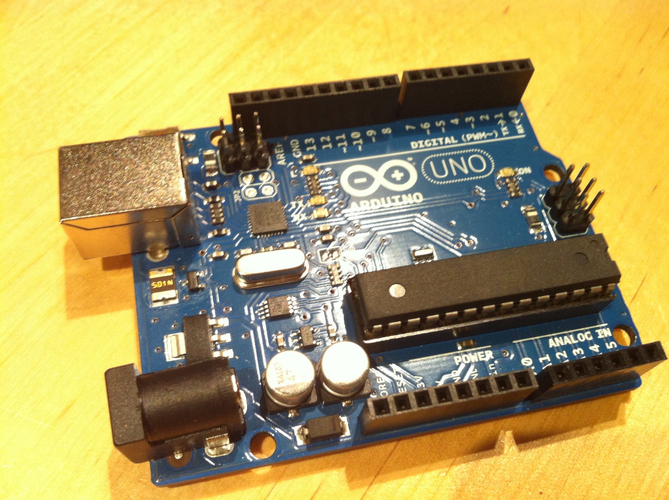
It uses an Electric Imp, an Adafruit Wave shield and an Arduino Uno
The Electric Imp enables you to quickly connect devices (including arduinos) to the internet through your Wifi network.
The Adafruit Wave shield makes it simple to play audio files from an SD card using an arduino.
When I first came across the Electric Imp I started wondering how I could combine it with an Arduino and make a fun remotely activated project. At around the same time I was also tinkering with the Adafruit wave shield and realised they'd make perfect companions.
In the end I decided to record myself saying a few different messages such as "I'm on my way home - get the kettle on!" so that I could trigger the messages as I left work. I figured this would be much more fun than the usual text message.
I built my "Imp-ersonator" into a photo frame in the living room so that I can trigger a message to be heard by whoever's at home when I'm leaving work (usually my wife or children but it occasionally freaks out visiting friends which is an added benefit...)
To build your own you'll need the following things:
1) Electric Imp Card
2) Electric Imp Shield for Arduino
3) a few jumper wires
4) Arduino Uno
5) Adafruit Wave Shield
6) 8 Ohm Speaker
7) soldering kit (solder, soldering iron, etc)
8) USB cable (A-B) for uploading code to the arduino
9) Photo frame that is deep enough to fit everything in
Step 1: Build the Wave Shield

The best way to build your Adafruit Wave shield is to follow Ladyada's fantastic tutorial.
You need to take care to format your SD card properly and then save your sound files onto it and make a note of the file names.
Obviously, they need to be .wav sound files.
If you are using iTunes there's information here on how to convert songs to the .wav format.
Solder your speaker to the shield as shown by the red and black wires in the photo.
Step 2: Add Jumper Wires to Imp Shield

Now you need to add some jumper wires to the Imp Shield so that the pins attached to the Imp will provide a signal to the appropriate pins on the arduino.
Because we're using an arduino Uno and the wave shield and imp shield use up quite a few pins there are only 3 left for triggering sound files. If you choose to use an Arduino Mega you'll be able to trigger a load more messages.
Connect the following pins:
Imp pin 5 to Arduino pin 0
Imp pin 7 to Arduino pin 7
Imp pin 9 to Arduino pin 6
If you want to use different pins that's fine but check which pins are used by the shields as some of them cannot be changed.
Step 3: Upload the Code to the Arduino
The Arduino code is a mashup of a basic Electric Imp example and the buttons example for the Wave Shield.
You need a library called WaveHC for the Wave Shield which you'll come across when you follow the Ladyada tutorial.
The first thing is to set up a serial connection with the Electric Imp so that any signals received can be used.
Then the code treats a signal received on one of the Imp pins as if it were a button being pressed. This in turn causes a sound file to be played from the SD card via the Wave Shield library.
Copy the code below and paste it into the Arduino IDE and upload it to the board:
/*
This code sets up a serial connection to an Electric Imp and triggers sound files to be played from an SD card when a signal is received from the Imp.
It's basically a mashup of the wave shield buttons example and the Electric imp basic arduino example
Pins:
8,9 for imp
Pins 13, 12 and 11 are used to talk to the SD card and cant be changed.
The rest of the pins, however, are more flexible.
2 -> LCS
3 -> CLK
4 -> DI
5 -> LAT
10 -> CCS
0 = onwayhome.wav
6 = friday.wav
7 = tea.wav
*/
//You need the WaveHC library
#include <FatReader.h>
#include <SdReader.h>
#include <avr/pgmspace.h>
#include "WaveUtil.h"
#include "WaveHC.h"
#include <SoftwareSerial.h>
//set up a serial conncetion for the Imp
SoftwareSerial impSerial(8, 9); // RX on 8, TX on 9
SdReader card; // This object holds the information for the card
FatVolume vol; // This holds the information for the partition on the card
FatReader root; // This holds the information for the filesystem on the card
FatReader f; // This holds the information for the file we're play
WaveHC wave; // This is the only wave (audio) object, since we will only play one at a time
#define DEBOUNCE 5 // button debouncer
// here is where we define the "buttons" that we'll use - in this case they are connected to pins on the Electric Imp
byte buttons[] = {6,0,7};
// This handy macro lets us determine how big the array up above is, by checking the size
#define NUMBUTTONS sizeof(buttons)
// we will track if a button is just pressed, just released, or 'pressed' (the current state)
volatile byte pressed[NUMBUTTONS], justpressed[NUMBUTTONS], justreleased[NUMBUTTONS];
// this handy function will return the number of bytes currently free in RAM, great for debugging!
int freeRam(void)
{
extern int __bss_end;
extern int *__brkval;
int free_memory;
if((int)__brkval == 0) {
free_memory = ((int)&free_memory) - ((int)&__bss_end);
}
else {
free_memory = ((int)&free_memory) - ((int)__brkval);
}
return free_memory;
}
void sdErrorCheck(void)
{
if (!card.errorCode()) return;
putstring("\n\rSD I/O error: ");
Serial.print(card.errorCode(), HEX);
putstring(", ");
Serial.println(card.errorData(), HEX);
while(1);
}
void setup() {
byte i;
// set up serial port
Serial.begin(19200);
putstring_nl("WaveHC with ");
Serial.print(NUMBUTTONS, DEC);
putstring_nl("buttons");
putstring("Free RAM: "); // This can help with debugging, running out of RAM is bad
Serial.println(freeRam()); // if this is under 150 bytes it may spell trouble!
// Set the output pins for the DAC control. This pins are defined in the library
pinMode(2, OUTPUT);
pinMode(3, OUTPUT);
pinMode(4, OUTPUT);
pinMode(5, OUTPUT);
// set the data rate for the SoftwareSerial port
impSerial.begin(19200);
// Make input & enable pull-up resistors on switch pins
for (i=0; i< NUMBUTTONS; i++) {
pinMode(buttons[i], INPUT);
digitalWrite(buttons[i], HIGH);
}
// if (!card.init(true)) { //play with 4 MHz spi if 8MHz isn't working for you
if (!card.init()) { //play with 8 MHz spi (default faster!)
putstring_nl("Card init. failed!"); // Something went wrong, lets print out why
sdErrorCheck();
while(1); // then 'halt' - do nothing!
}
// enable optimize read - some cards may timeout. Disable if you're having problems
card.partialBlockRead(true);
// Now we will look for a FAT partition!
uint8_t part;
for (part = 0; part < 5; part++) { // we have up to 5 slots to look in
if (vol.init(card, part))
break; // we found one, lets bail
}
if (part == 5) { // if we ended up not finding one :(
putstring_nl("No valid FAT partition!");
sdErrorCheck(); // Something went wrong, lets print out why
while(1); // then 'halt' - do nothing!
}
// Lets tell the user about what we found
putstring("Using partition ");
Serial.print(part, DEC);
putstring(", type is FAT");
Serial.println(vol.fatType(),DEC); // FAT16 or FAT32?
// Try to open the root directory
if (!root.openRoot(vol)) {
putstring_nl("Can't open root dir!"); // Something went wrong,
while(1); // then 'halt' - do nothing!
}
// Whew! We got past the tough parts.
putstring_nl("Ready!");
TCCR2A = 0;
TCCR2B = 1<<CS22 | 1<<CS21 | 1<<CS20;
//Timer2 Overflow Interrupt Enable
TIMSK2 |= 1<<TOIE2;
}
SIGNAL(TIMER2_OVF_vect) {
check_switches();
}
void check_switches()
{
static byte previousstate[NUMBUTTONS];
static byte currentstate[NUMBUTTONS];
byte index;
for (index = 0; index < NUMBUTTONS; index++) {
currentstate[index] = digitalRead(buttons[index]); // read the button
/*
Serial.print(index, DEC);
Serial.print(": cstate=");
Serial.print(currentstate[index], DEC);
Serial.print(", pstate=");
Serial.print(previousstate[index], DEC);
Serial.print(", press=");
*/
if (currentstate[index] == previousstate[index]) {
if ((pressed[index] == LOW) && (currentstate[index] == LOW)) {
// just pressed
justpressed[index] = 1;
}
else if ((pressed[index] == HIGH) && (currentstate[index] == HIGH)) {
// just released
justreleased[index] = 1;
}
pressed[index] = !currentstate[index]; // remember, digital HIGH means NOT pressed
}
//Serial.println(pressed[index], DEC);
previousstate[index] = currentstate[index]; // keep a running tally of the buttons
}
}
void loop() {
// Send data from the software serial
if (impSerial.available())
Serial.write(impSerial.read()); // to the hardware serial
// Send data from the hardware serial
if (Serial.available())
impSerial.write(Serial.read()); // to the software serial
byte i;
if (justpressed[0]) {
justpressed[0] = 0;
//Serial.println("pin 6 triggered");
playcomplete("home.wav");
}
if (justpressed[1]) {
justpressed[1] = 0;
//Serial.println("pin 0 triggered");
playcomplete("friday.wav");
}
if (justpressed[2]) {
justpressed[2] = 0;
//Serial.println("pin 7 triggered");
playcomplete("tea.wav");
}
/*
if (justpressed[3]) {
justpressed[3] = 0;
playcomplete("Your Song.wav");
}
if (justpressed[4]) {
justpressed[4] = 0;
playcomplete("Your Song.wav");
}
if (justpressed[5]) {
justpressed[5] = 0;
playcomplete("Your Song.wav");
}
*/
}
// Plays a full file from beginning to end with no pause.
void playcomplete(char *name) {
// call our helper to find and play this name
playfile(name);
while (wave.isplaying) {
// do nothing while its playing
}
// now its done playing
}
void playfile(char *name) {
// see if the wave object is currently doing something
if (wave.isplaying) {// already playing something, so stop it!
wave.stop(); // stop it
}
// look in the root directory and open the file
if (!f.open(root, name)) {
putstring("Couldn't open file "); Serial.print(name); return;
}
// OK read the file and turn it into a wave object
if (!wave.create(f)) {
putstring_nl("Not a valid WAV"); return;
}
// ok time to play! start playback
wave.play();
}
Step 4: Stack the Shields Onto the Arduino

Probably the easiest step of all of them!
Stack the Wave shield onto the arduino and then the Imp shield onto the Wave Shield
Step 5: Set Up the Electric Imp and Upload Code Using the Imp Planner

Follow the instructions that come with your Electric Imp card to set it up with your WiFi network.
This involves powering it from the Imp Shield (just plug the arduino stack into your computer with a USB cable) and using the Electric Imp App to flash the details to the card. This is done using a series of blinks on the smartphone screen so you don't need any special cables for this part.
You also need to sign up on the electric imp website so that you can use the Imp Planner.
Once you're logged in you can click on the impees tab and you should see a reference to your Imp.
Click on the Code tab followed by + to create a new imp code unit. Enter a name for your code (I used Trigger) then click OK. You will then be taken to the code editor. Copy and paste the code below into the code editor.
It's a pretty simple bit of code that adapts one of the very basic examples in the Imp tutorial section. The main difference is that there are three hardware pins that can be triggered by an input from a webpage These are the pins connected to the arduino that in turn trigger the sound files. With your commissioned Imp powered up you can click on what looks like a play button and the code is uploaded to the Imp over Wifi. This is a great bonus of the Imp - you can update code remotely and on the fly from anywhere that has an internet connection.
So how do we achieve the all important connection to the internet for our device?
Click on the Planner tab and you should see a single blue node titled Trigger. This is your imp that you have uploaded the Trigger code to. Now click on Add Node and choose HTTP IN. Drag a line from this node and connect it to the Trigger node. An arrow will appear and then a pop-up box. Click connect.
Then click on the top right hand corner of the node and copy the web address which you will need in the next step. It will be something like https://api.electricimp.com/v1/xxxxxxxxxxxxx/xxxxxxxxxxx
One of the things I learned after a few first unsuccessful attempts to get this all to work was the importance of having a "watchdog" function in the imp code. This makes sure that the imp "wakes up" and secures its connection to the server. Without this the imp is automatically disconnected from the server after a period of time.
//Imp-ersonator trigger code
// remotely trigger one of 3 messages from a wave shield via SD card using arduino
function pinOff()
{
hardware.pin9.write(1); //writing 1 turns trigger pin off
hardware.pin7.write(1) ; //writing 1 turns trigger pin off
hardware.pin5.write(1); //writing 1 turns trigger pin off
}
// input class for trigger control channel
class input extends InputPort
{
name = "TRIGGER"
type = "number"
function set(value)
{
if(value == 0)
{
hardware.pin9.write(1); //writing 1 turns trigger pin off
hardware.pin7.write(1) ; //writing 1 turns trigger pin off
hardware.pin5.write(1); //writing 1 turns trigger pin off
}
if(value ==1)
{
//write pin low
hardware.pin9.write(0); //writing 0 turns trigger pin on
//wait 1 second then turn pin off
imp.wakeup(1.0, pinOff);
}
if(value ==2)
{
hardware.pin7.write(0); //writing 0 turns trigger pin on
//wait 1 second then turn pin off
imp.wakeup(1.0, pinOff);
}
if(value ==3)
{
hardware.pin5.write(0) //writing 0 turns trigger pin on
//wait 1 second then turn pin off
imp.wakeup(1.0, pinOff);
}
}
}
// Configure pin 9,7 and 5 as an open drain output with internal pull up
hardware.pin9.configure(DIGITAL_OUT_OD_PULLUP);
hardware.pin7.configure(DIGITAL_OUT_OD_PULLUP);
hardware.pin5.configure(DIGITAL_OUT_OD_PULLUP);
//set to high initially
hardware.pin5.write(1);
hardware.pin7.write(1);
hardware.pin9.write(1);
function watchdog() {
imp.wakeup(5*60, watchdog);
server.log("watchdog");
}
// Register with the server
imp.configure("TRIGGER", [input()], []);
watchdog();
// End of code.
Attachments

Step 6: Test Your Device and Create Web Pages As Shortcuts on a Smartphone

So, now you have your device set up to receive a signal from a webpage and this will tell the Imp to change the state of one of three pins on the arduino which in turn will play one of the sound files.
So how do we use a webpage to determine which of the sound files to play?
Simply type your web address from the HTTP IN node and add /?value=1 at the end. Change the number from 1 to 2 or 3 to trigger each sound file.
You can test this from any web browser and then when you're happy it's working type each web address into the browser on your smartphone and use the option to save the page as a bookmark. On the iPhone you can create these bookmarks as little icons that resemble apps on your screen. Name them in such a way that you know at a glance which message you will trigger and you're done!
Step 7: Try It Out!

Participated in the
Instructables Design Competition


