

Introduction: IV Curve Tracer


*** Do not attempt this project if you are not comfortable working with line voltages! ***
This projects shows how to create an IV (Current and Voltage) Tracer that can be used to teach the electrical characteristics of a solar panel.
This project was created as part of an Electrical and Computer Engineering capstone project at The Ohio State University.
Step 1: What We Used for This Project
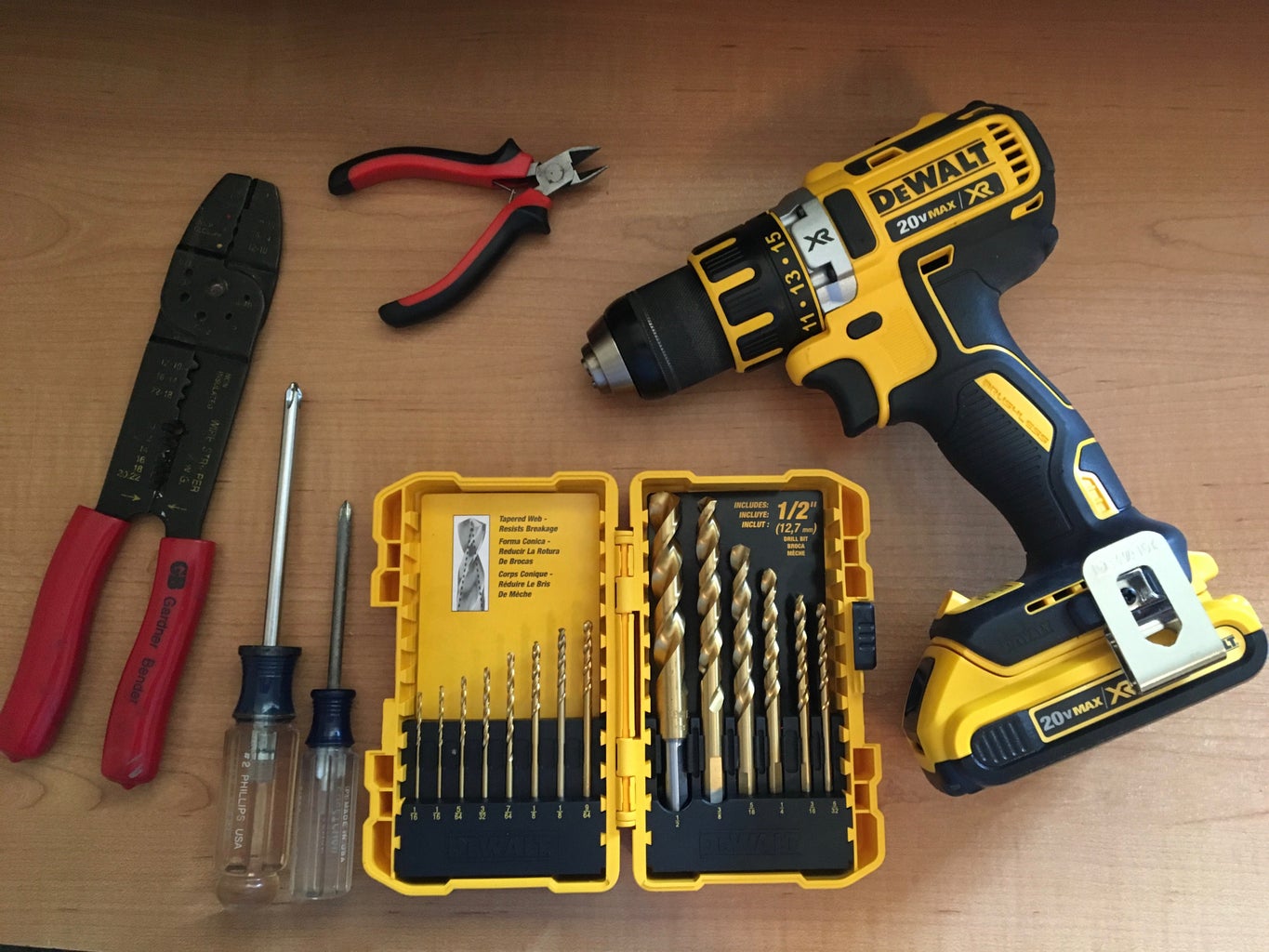
Tools:
- Drill
- Drill Bits
- Philips Screwdriver
- Soldering Iron
- Wirestrippers
- Needle Nosed Pliers
- Banana Jack Test Leads
Parts:
See the parts list for a complete list as well as links for all the parts.
Attachments

Step 2: Order Your Circuit Board.
We used Advanced Circuits for our circuit board, but you are welcome to use any PCB shop you like.
If you do not already have Eagle Cad installed on your computer, use the link below to install the free version.
http://www.cadsoftusa.com/download-eagle/?CMP=KNC-GUS-FUS-GEN-SUP-CAD-Eeagle-CAD
Attachments

Step 3: Drill Holes for the Power Supply.


Using the bottom of the power supply as a templet, drill 4 holes large enough for the M4 machine screws though the bottom on the hefty shoe box.
Step 4: Mount the Arduino Uno.


Using a philips head screw driver, remove the top honeycomb cover from the power supply. Mount 4 of the M3 PCB spacers on the honeycomb using M4 washers to prevent the nylon spacer nuts from slipping through the honeycomb.Then use another set of spacers to secure the Arduino to the power supply cover. Take care to ensure the Arduino is not contacting the metal cover as this may cause a short circuit.
Step 5: Solder the Components to the PCB.

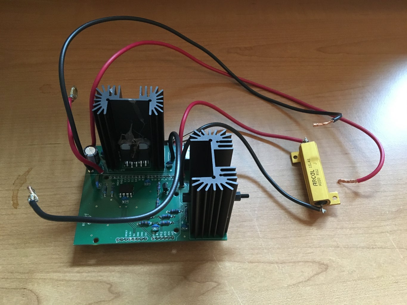
- Using the included schematic as a guide, soldered the op-amps, resistors, capacitors, wires, and the DAC to the board.
- Coat the back of both op-amps with an even coverage of thermal compound taking care not to get the compound on the op-amp pins.
- Position the heatsinks behind both op-amp, and use some extra PCB spacers to secure the heatsinks to the op-amps.
- Solder the pins of the heatsinks to the board. Be patient as it will take a large amount of heat to bring the pins up to the right temperature for the solder to melt.
Attachments
Step 6: Mount the PCB on Top of the Arduino Uno.

- Plug the headers of the completed circuit board into the Arduino and use 3 nylon M3 PCB screws to secure the board to the PCB spacers.
- Using the M3 nylon PCB screws and nuts, attach the 50W resistor to the honeycomb as shown in the included picture using the M4 washers to prevent the screws from pulling through the honeycomb.
- Secure the cover back on the power supply.
- Connect the GND and 24+ red and black wires to the V+ and V- terminals on the power supply using a philips screwdriver.
Step 7: Mount the Arduino Uno and Power Supply Inside the Enclosure.


- Secure the power supply and board assembly inside the enclosure as shown in the pictures using the M4 machine screws and washers with 8 Nylon washers holding the power supply above the bottom of the enclosure. You can use this extra scape to route your connecting wires as shown in the picture.
- Using a permanent marker, mark holes for the USB port, the banana jack test ports, and the PG9 cable gland.
- Add extra holes for ventilation as shown in the pictures.
- Remove the power supply and board assembly from the enclosure.
- Use a drill to create holes at each point you have marked.
Step 8: Drill Holes in the Enclosure.


Using the fan as a guide drill both the mounting holes for the fan as well as holes in the area enclosed by the fan as shown in the picture. Be sure to have the fan towards the top side of the enclosure to allow room for the power supply below it.
Step 9: Connect the Power Cord and Test Terminals.


- Secure the power supply and board assembly back in the enclosure.
- Take an AC power cord with a ground prong and strip 1 foot of the outer jacket off as shown in the picture.
- attach the PG9 cable gland to the cord at the point where the outer jacket has been stripped off.
- Expose a 1/2 inch of copper on the ground, line, and neutral wires.
- Secure the cable gland to the exterior of the enclosure and connect the ground, line, and neutral wires to the power supply.
- Connect the SP+ and SP- red and black wires to the red and black test ports on the enclosure.
Step 10: Mount the Fan.


- Connect the red and black power wires of the fan to the V+, and V- ports on the power supply.
- Mount the fan to the inside of the enclosure using M4 machine screws, washers, and nuts taking care to ensure the direction arrow on the side of the fan points toward the inside of the enclosure. This will ensure the fan is forcing air into the enclosure.
- Attach the lid to the top of the enclose.
Step 11: Load the Firmware Onto the Arduino Uno.

If you have not already installed the Arduino IDE, go to https://www.arduino.cc/en/Main/Software and install the IDE on your computer.
- Open the included IVCruveTracer.ino file using the Arduino IDE.
- Connect the IV Curve Tracer to the computer using a USB cord and the USB port on the Arduino.
- Select the Arduino Uno board by going to Tools, Board, and selecting the Arduino Uno. Then select the Com port the Arduino is using by going to Tools, and then Port.
- Click the Upload button (right pointing arrow) and wait for the IDE to finish uploading the firmware.
- Close the Arduino IDE.
Attachments
Step 12: Install the IV Curve Tracer Software.
Install the IV Curve Tracer software included with this step. The installer may ask you to update or install Microsoft .net framework.
Attachments
Step 13: Connect the IV Curve Tracer Software to the Arduino.

Open the IV Curve Tracer software and select the Com port your Arduino is connected to using the dropdown menu on the top right corner of the interface.
Open the Connect/Disconnect Menu on the top left side of the interface and click Connect. The Capture button will become visible and the software is now ready to plot a curve.
Step 14: Connect the IV Curve Tracer to a Solar Cell.

Plug the AC power cord into an outlet and connect the solar panel to the banana plug test ports using test leads. Connect the positive side of the solar cell to the red test port and the negative side of the cell to the black test port.
Step 15: Plot a Curve.
Select the start and end voltage for the plot using the sliders located below the Clear button. Next click the Capture button and a curve will be drawn on the graph. You can plot up to 5 curves on the same graph.
Step 16: Extra Material.

The included lesson plan may be used to teach a class about the characteristics of solar cells.
The code for the PC application that plots the curves is also included and can be edited using Microsoft Visual Studio Free Community Edition.


