

Introduction: IOS/Android Remote Controlled Blimp With Video Feedback


This project was the eye catcher of my Artist In Residency at Instructables.
As RC blimps are my passion, I definitely wanted to do some blimp project during my stay at Instructables. When I came across the Dension WIRC system, the lingering idea of building one with live video feedback became a real plan. The Dension WIRC (for Wi-Fi Remote Control) is a plug-and-play system to control remote control models with an iOS or Android device and send a live video stream to the device.
It is very easy to set up and use, but at about a 100g, it is rather heavy compared to my other blimp projects. Taking in account an extra 100g for propulsion, batteries and construction, I went looking for a readily available balloon with a lift capacity of over 200g. A 3ft latex balloon turned out to balloon carry 180g to 330g depending on the diameter it’s inflated to (2.5ft resp. 3ft). It also turns out these balloons can hold for weeks, coming close to the performance of foil balloons.
From the spherical shape (and from watching Doctor Who) sprung the idea to make it into a large eye. I named it ‘In the Blimp of an Eye”.
I tried to keep the build as simple as possible to make sure to have a functional end result. I was a success, be it that it is very sensitive to drafts and controlling it was quite a challenge. I will discuss some ideas to improve on that throughout this Instructable.
Here is video (I converted the recorded mjpeg with VLC, but with quite some quality loss):
I dedicate this Ible to Noah, for managing the AIR program like an unstoppable force of nature during the very busy time involved with moving Instructables to Pier 9 and at the same time being a warm host to us artists.
And I thank Audrey for the great main picture.
Step 1: Materials and Tools


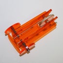
- A Dension WIRC system complete with Wi-Fi dongle and USB camera.
- An iPhone, iPod, iPad or Android device.
- Three analogue micro servos. I started with the 8g Turnigy 1800A Servos, but replaced one with a slightly more powerful Radio Shack micro servo. After this build I would recommend slightly more powerful servos (like 13g ones).
- I tried a gyro (a HobbyKing BA Nano Gyro 2.3gram) to improve flying straight out, but I’m not convinced it helped at all.
- A servo extension cord at least 15cm long (I used ones far longer than needed).
- Connectors and wires (two times) to go from the battery connectors (classic red JST ones in my case) to the WIRC sockets (the WIRC accepts Futaba or JST type servo plugs).
Batteries:
- A 2s Lipo pack minimum 250mah. I used a Turnigy nano-tech 260mah 2S 35~70C Lipo Pack but it broke down immediately, so I switched to ZIPPY Compact 350mAh 2S 25C Lipo Pack
- An additional 1s Lipo (I used a ZIPPY 240mAh 30C Single Cell) or a 1.5 A BEC ore use 7.4 V compatible servos.
- A suitable charger
Materials:
- A 3 ft. latex balloon, white (I got mine at SF Party).
- Helium, one fill needs 0.35 Nm3. A large one-way tank would be cutting it close, not leaving any room for error or experimenting. Also helium in one-way tanks is usually only about 85% pure, giving less pure an it’s quite expensive. So I recommend to have the balloon filled at the balloon shop if you can transport it safely or to rent a tank.
- High-Float to treat the balloon for a better helium retention.
- Optional: balloon shine for … keeping the balloon shiny.
- Gap filling CA glue (i.e. medium thickness).
- A piece of extruded polystyrene sheet (commonly known under the brand name Depron). You can use a 3 to 6 mm thick sheet, the size of the iris, about 40 cm in diameter.
- A roll of Sellotape (Scotch tape).
- Some thin double sided tape.
- Acrylic paint, black and whatever colours you want to use for the iris.
- Some string to close the balloon and holding it down when working on it.
- Some non-hardening clay (putty) as ballast to trim the buoyancy.
- For the frame I used plywood, 4 mm thick, 30 by 80 cm.
Total costs amount to about $ 300 to 400 depending on sourcing and not counting the iOS or Android device obviously. All gear but the Dension WIRC was available at the Hobbyking US warehouse.
Tools:
- A Phillips 0 or 00 screwdriver to hack micro servos
- A pump or compressor to pre-inflate the balloon
- A hobby knife
- Some fairly fine grit sandpaper
- A small paintbrush
- I used a laser cutter to make the frame, but I will discuss alternatives.
- I used an Objet 3D printer to make the propellers, but you can buy and use small and cheap propellers like these.
Step 2: The WIRC System


The manual for the WIRC is quite clear (and available here). Setting up the system was easy. There are two things I want to add:
- You need to switch the profile to “advanced” to have more than two channels available.
- The recorded videos are in mjpeg format, but the dot is missing before the mjpeg extension. Add it for programs like VLC to recognize it.
Before using it in the blimp project I made a quick test setup with some cardboard, a continuous rotation servo to pan and micro servo to tilt (as shown in the last picture).
The WIRC system allows any connection between the RC channels and either the tilting of the controlling smart device or sliders on the touch screen. For the blimp I chose the sliders as it is mainly controlled with bursts from the motors and switching of the motors The touch screen sliders automatically return to neutral, while it hard to find the neutral when tilting. After all, when using hacked servos, the “neutral range” is very narrow (see Step 6).
I found an iPad gives somewhat better control, because the slider controls are slightly larger (only slightly, not proportional to the screen size).
I choose to put the up/down on a touch screen slider “joystick” on one side and the forwards/backwards + the left/right on the other slider “joystick”. I did this, because mostly you want the altitude constant and not accidentally influenced by movements of the other joystick movements.
You can find the WIRC profile (settings file) I used attached.
Attachments

Step 3: Mass and Lift Capacity


I started out weighing the WIRC set as a whole and each main component, the camera being the heaviest. But the camera has this lumpy plastic clamp of which a part can easily be removed by loosening some screws. Actually the packaging and cables show a lot of potential to hack them and loosing a lot of weight. But I decided not to do that on this first build, not risking the system not working properly anymore. I plan to do that on a second WIRC.
So I ended up with a control and video feedback system just under a 100 g.
Then I weighed the other RC components: servo’s, batteries and extension cords and everything together. Note that at that time I was still thinking to use a fourth servo (the white one) to tilt the camera, which I later dropped to keep it simple. I was at 172g
I pre-inflated the balloon with air to its desired size, which was determined by the maximum diameter still passing a common door. I tested a plastic clamp holding it closed and not being very impressed with it decided afterwards to use some string.
I left the air out and put in a good blob of “Hi-Float”, rubbing it out al over the inner surface. Then I inflated the balloon with helium to the same size again.
I checked the lift capacity by subtracting the weight from the ballast with the balloon pulling upwards from the weight when holding the balloon down by hand: 260g. So there was still plenty of room for the iris, a frame, small parts like the propellers and margin for loss of helium over time.
Step 4: The Frame


The frame should be light, stiff and to some degree follow to the curve of the balloon surface. I first thought about layering some thin wood strips or carbon rods and gluing them together in a curved shape (still a good alternative), but I explored making a frame by laser cutting a frame out of plywood. At 17 g it turned out rather heavy, but acceptable in frame of the total mass already involved. It also turned out easy to adapt when I dropped the push prop at the back for a propeller at the front to improve the stability when flying straight forward.
I designed the frame in Inkscape, but I had trouble making an open lattice based on tiled shapes. So I switched to make design based on intersecting circles with an adapted “star” shape with a lot of rounded “spikes”. I saved the result as a pdf (added to this step) to go to the laser cutter.

Step 5: Propellers


The choice of propellers is not very critical for the power level used. However, with the propulsion concept used, it is nice to have propeller blades with a flat profile. Giving the same efficiency and therefor thrust in both spinning directions. This is particularly good for the tail rotor. As Randofo had already made 3D printed propellers I decided to do the same, starting from his design made in 123D Design (Both the 123D and the stl file are attached to this step, thank you Randy). Actually I only adapted the axle hole to the diameter of my motor axles (0.75 mm) and printed out in two diameters like Randofo already designed. I printed them in an ABS like material on an Objet printer, giving very tough propellers. The smaller diameter turned out to work best with the Turnigy 1800A servos. For the Radio Shack micro servo the difference in thrust between both propellers was smaller and I used the larger diameter because I prefer the lower rpm that go with that.
Don’t worry if you cannot 3D print the props. You can use small and cheap propellers like these.
These do give a difference in thrust according to the spinning direction, but that still works. And if the axle hole is too large you can put in a layer of CA glue as explained in Step 6 of this Ible of mine.
Attachments
Step 6: Hacking the Micro Servos


As in many of my RC blimp projects I used hacked servos for propulsion and control.
It is important to choose analogue servos. We are using the servo electronics as simple reversing speed controllers. The wider “neutral” gap and somewhat proportional response, making the analogue servos less accurate than digital ones, is an advantage in this case. A hacked digital servo would be very difficult to trim to standing still and would practically immediately go to full speed in either direction.
Note the “power off band” is still very narrow with any good analogue servo, so often the motors will keep humming and/or spin slowly. That doesn’t hamper controlling the blimp. I you really want to get rid of that you could double de servo circuits like I did in step 7 of this Ible.
The “neutral” (not running) position of the controls can be trimmed in two ways: either with the potentiometer from the servo, or the settings on the controlling device. I prefer to keep the neutral settings on the device neutral and trim the potentiometer so the motor doesn’t run at that control position. In-flight corrections can still be done on the controlling device.
The servos are opened and the complete casing and gearing is removed. For the motor and potentiometer that can be a bit tricky: don’t pull on the wires, but push on the axle to get the parts out of the casing. If you are unsure on the forces you can put on the axles, you can also carefully cut away the casing with small cutting pliers.
Once the parts are out, the electronics are protected with some tape. Tape the wires in to, so when you pull on the wires you pull on the complete unit and don’t pull of the wires.
I started the build with 8g Turnigy 1800A Servos, but the blimp remained underpowered. I tested different prop sizes, but as the blimp has a huge surface area and air currents from the airco constantly brought it in trouble. When making sure there are no drafts, control was possible after some practice.
I tried the servos on 7.4 V, but overheated a motor. I went back to 3.7 V and replaced one with a slightly more powerful Radio Shack micro servo (with a larger prop). I chose to replace the up/down motor because that is the most critical movement in most rooms (most often the available height is smallest dimension) After this build I would recommend slightly more powerful servo’s (like 13g ones), and preferably ones that can work on 7.4 V.
Step 7: Propulsion Configuration


I chose one of the simplest setups possible: one motor directed vertically for up down, one horizontally for forwards/backwards and one “tail rotor” positioned perpendicularly at the back for turning left and right (first two pictures show there positions in the final build).
You can find more on this setup in this Ible of mine. https://www.instructables.com/id/Sub-Micro-Blimp/
The motors are attached to the frame with some elastic bands end fixed in place with a drop of CA glue. Take care not to get any glue on the axle.
I tried a gyro on the tail rotor to improve flying straight out, but I’m not convinced it helped at all. The gain was far too small, giving only low power thrust even when giving fast twist to left or right by hand (of course on helicopters and such small corrections are what is needed). The tail rotor configuration works well for that. Maybe a programmable gyro could allow for more gain. Or I could add a (clear) fin at the back. But actually flying more or less straight out was not as hard as I expected with the round shape, provided there are no strong drafts.
Step 8: The Iris


I wanted an iris that is easily mounted when changing the balloon. The iris is made out of piece of extruded polystyrene sheet (commonly known under the Brand name Depron). At about 1.2 g /dm2 it is one of the lightest stiff and smooth materials available).
I used 3mm thick sheet as I had only that available, but it is my experience 6mm is hardly heavier and is easier to bring in a double curved shape.
I marked out a circle with the classic string method. You could do the same for a smaller circle for the pupil, but I used a round bowl as template (not shown). The circle is cut out with a hobby knife and the edges are sanded smooth.
The cutout you see in the pictures was actually too large. I made it smaller expecting the latex balloon to shrink noticeable over days, but actually it held for weeks, so the iris turned out a bit smallish compared to the eyeball.
To bring the extrude polystyrene in a double curved, more or less spherical shape I laid the part on a cushion and rolled a ball on the surface in spiralling movements and applying force (the pictures also show a small test I did first). The extrusion direction is clearly noticeable as the material curves more easily in one direction than the other, but I got a shape that could be held down on the balloon surface.
I painted the pupil black (actually it easiest to that last) and the iris I did with blue, green and dark brown, painting in stripes while the different colours are still wet.
I made sure the edges are well covered, with a darker edge.
Using thin double side tape, I taped the iris to the balloon, on the opposite side of the tied opening. The less curved sides did tend to loosen after a couple of days, but could easily be stuck on again. I am planning to use stronger “carpet grade” double-sided tape when putting in a new balloon.
Step 9: Assembly and Flying


The camera is taped to the frame, at the front. The WIRC unit is taped in place fairly far to the back to keep it in balance. The Wi-Fi dongle is left hanging loose, and gets its place later, its position helping to get the right balance. Some elastic bands are put ready near the middle, for the batteries.
The servos are connected to the WRC unit. I could actually do with one extension cord, as the gyro on the tail rotor also provides an extension.
The WIRC has to separate power circuits, on for the unit itself, needing 5.5 V at least and one for the servos. You could use one 5.5 – 6 V power source for both, but where as the unit itself thrives well on a 7.4 V 2s Lipo, for most micro servos that is too much (I did burn one). You could look for micro servo’s holding up to 7.4 V (my plan for a next build) or use a 1.5 A 5 V BEC but I simply added a 1s Lipo. Note that in contrast to almost any RC builds we have here a receiver unit at a higher voltage than the propulsion system, which are the servos in this case (In a classic setup the WIRC will take the higher voltage from the main battery and power the steering servos from the ESC’s BEC).
I made two power cables to go from the batteries to the row of servo pins power pins respectively to the WIRC power pins (servo type plug). I marked one with tape to tell them apart, but there is no big problem when mixing them up. The WIRC unit will not work (well) on 3.7 V and the in this situation the motors will not run (long) and therefor not overheat from being fed 7.4V.
Power up and check the neutral position (power off) of the motors and trim with of the potentiometers when needed. Put on the propellers and check the spinning direction corresponding to the controls. Reverse direction on the controlling device when needed.
When using a gyro I find it is easiest to first trim that to neutral (hanging it in the position prescribed by its manual) and then connect the tail rotor and trim its potentiometer. I you need to reverse the gyro response turn it upside down and re-attach.
At this stage the frame is taped to the balloon at three places. The back end, with the tail rotor, should come out fairly high and with enough distance from the balloon to have the propeller spin freely. Again, I was expecting the balloon to shrink more. A small piece of Depron can help keeping the distance needed.
Non-hardening clay is added as ballast till the blimp just slowly sinks when no power is applied.
You’re ready for a first test flight. I left a piece of string hanging for grabbing it in emergencies and for easy anchoring.
It turned out harder to fly than many of my other RC blimps. I also had limited time to practice in good conditions (with the airco off). But I started to more or less control it. I am planning e new build, with a stripped down WIRC (saving weight), allowing for a balloon inflated to slightly smaller diameter (and therefor a smaller surface area). I will also try slightly heavier, more powerful servos, running on a higher voltage (also saving the weight of an extra battery). I also consider using vectored thrust, still my preferred propulsion setup for larger blimps (see this Ible)

Participated in the
Halloween Decorations Contest


