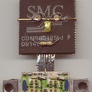
Introduction: In-line Headphone Amplifier
Powered by a single AAA cell,this amplifier is scarcely thicker than the audio cable and fits between the line out socket of your PC sound card and your headphones. Most sound cards have line level outputs, at high impedance, and will not drive headphones directly at full volume.
It is based on the headphone amplifier chip from Maxim, the MAX9725, which can work at voltages as little as 0.9 volts (range 0.9 to 1.8 volts).
This chip does not need capacitors on its output since it has directly coupled output stages and it generates a negative supply rail by using an internal switchmode power supply stage.
This is a small surface mount chip and can be placed by automatic equipment onto a suitable printed circuit board.
I am using wires on a hand carved board, and am presenting my steps here in the hope that it will inspire somebody out there to try something similiar with the tiny chips those guys insist on manufacturing - great features, but a tiny package.
Step 1: Circuit Board
The circuit has to be assembled on a circuit board. I find that a piece broken off a larger board will be sufficient. It has green solder mask on, in fact it is part of a large Y/C panel from an old VCR.
Step 2: The Cabinet
It will need something to hold the circuit board, a battery and the headphone socket. I shall use a AAA cell to power it, and use the metal cladding from two AA cells to fabricate a suitable cover for these.
It is the only way to end up with an assembly little thicker than the battery powering it.
The picture shows the metal cladding being liberated from a couple of dead AA cells.
Step 3: Cutting the Board to Size
The board has been cut and filed to make it about as wide as a AAA cell.
Step 4: The Circuit
The figure shows the circuit, which has been unashamedly copied from the datasheet published by MAXIM for their chip. In addition to the chip and battery, five capacitors need to be fitted.
It would all be very easy, but the chip is intended for surface mounting and very small.
Step 5: Whittle a Circuit Board
A small (jewellers') screwdriver was sharpened into a chisel and a recess dug out of the component side of the circuit board. This board is made of paper laminated with phenolic resin, and it cuts with the chisel very easily. And I like the feel of cutting through it - absolutely unnecessary for the proper functioning of the circuit, I am sure, but it gives me something to do and makes the finished product look as if somebody spent some time on it.
This might be realised, for bulk manufacturing, by laminating laser cut paper and foil.
Step 6: Wiring Scheme
I shall be looking at the underside of the chip, so a scheme of connections is prepared looking at the chip that way.
The data sheets show the connections looking down at the top of the chip, and it is possible to make mistakes if wiring directly from that.
The view below has been labelled "bot view" and the board shows the chip securely inside its recess, and a few holes drilled for the connecting wires.
Step 7: The Other Side
The other side of the board shows the holes, the solder resist scraped away for the wires that connect to ground, and the copper bevelled away for those wires which do not.
Step 8: Soldering Wires
Two wires that connect to ground have been soldered in this picture.
Step 9: Soldering to the Chip
It needs a steady hand, a fine tip on the soldering iron, and good lighting in order to place the wires and solder exactly where they have to go.
The other end of the wires have been soldered to the foil and so they stay put while they are bent over the chip, cut to size and soldered to the pads.
I use a watchmaker's eyeglass for this part of the proceedings in order to see what I am doing.
Step 10: The Capacitors
Two capacitors from old hard disk drives have been liberated to be used in this circuit.
I have drilled a few more holes, and cut a few channels for the wires in this picture.
Both those capacitors are tantalum, surface mount, 1 microfarad.
Step 11: In Position
The capacitors have been soldered in position in this picture.
Step 12: More Capacitors
The capacitor for decoupling the power supply has been connnected up, this time it is on the same side as the chip.
Step 13: A Size Check
I have doubts whether everything will fit in the small volume, so it is time for a size check with the input capacitors and the headphone socket.
The capacitors are OK, but the headphone socket is larger than the thickness of the AAA cell.
Step 14: The Completed Board
The circuit board is complete, with the input coupling capacitors placed on either side of the board.
It is still smaller than a AAA cell.
Step 15: Tinplate Cabinet
This is one shell of a AA cell. Two such shells were soldered together.
Step 16: Ready for Bending
The two AA shells soldered together is ready for cutting and bending to form the AAA cell holder.
Step 17: Wired for Sound
The two wires carry the signal to the headphone socket at one end from the amplifier chip at the other, past the AAA cell held securely in between.
Step 18: Socket for Headphones
The socket for the headphones is to be made of parts from an old one to fit in the diameter of the AAA cell.
Step 19: Tip Connector Fitted
The spring connector contacting the tip of the jack has been fitted.
Step 20: Tip and Ring Contacts Fitted
The tip contact was modified, and the contact for the ring on the jack has been fitted.
Step 21: It Fits!
The jack inserted into the completed socket. It seems to be okay. It has to be inserted with a bit of Tender Loving Care or the thing might come apart.
Step 22: Trial Fit
The AAA cell and socket inside the metal cabinet. The cell looks mangled because I used it as a template to bend the sheet metal.
Step 23: Battery Spring
The spring contact for the battery negative is next soldered in. The picture shows the earphones I am using to test this with.
Step 24: Positive Contact Fitted
The positive contact for the battery is a piece of double sided copper clad board. The side which contacts the battery has clearance cut along the edges so that the battery does not short out to the case. The other side is soldered to the case.
Both the spring and the positive battery contact were taken from a defunct TV remote.
Step 25: It Is Complete
The headphone amplifier is complete, and it works.
The chip I used has a gain of 2 so it needs line levels (around a volt rms) in order to work.
With no signal, the current drawn from the battery was about 2 milliamperes. With the music blasting at a comfortable volume in the earphones shown the current went up to around 12 milliamps.
I should wrap it up in duck tape to make it look nicer, but it looks like the junk it was made from.
I shall try building it into a marker pen body the next time I get the urge to make one.


