

Introduction: Interactive LED Lab Coat


Check out the videos below! The first is a demo of the colors actuated by the buttons. The second is a demo of the breathalyzer! (this will be explained later)
Tools
- Sewing machine
- Soldering iron
- Wire cutters & strippers
- Hobby knife
- Hot glue gun
- Computer
Materials
- Two lab coats
- Arduino (Uno or later)
- LED Spool(s) (5 meter, 300 LED count, 50/50 size LEDs, epoxy-coated) - 2 spools for a child's coat, 3 for an adult.
- 24 gauge 4-wire strips (Intercom wire works well.)
- Protoboards (Or a ProtoShield for the Arduino will work even better. We cut our own protoboard to size and tucked it behind, because we wanted to keep the arduino visible. But a real protoshield would be more stable.)
- Sensors, to taste. Our code and wiring diagrams include a microphone, so your coat can light up in response to noise, and an accelerometer so your coat can light up as you move.
- 12 volt rechargeable battery packs. For a few hours of use, 2 or 3 packs for a child sized coat, 3 or 4 for an adult coat (this is to make sure there is enough amperage, each battery is limited to 2A max)
- Push-buttons
- Hot glue
- Solder
- Masking tape
- A white zipper (long enough to run the length of your coat)
- Velcro
Step 1: Plot the Light Strips
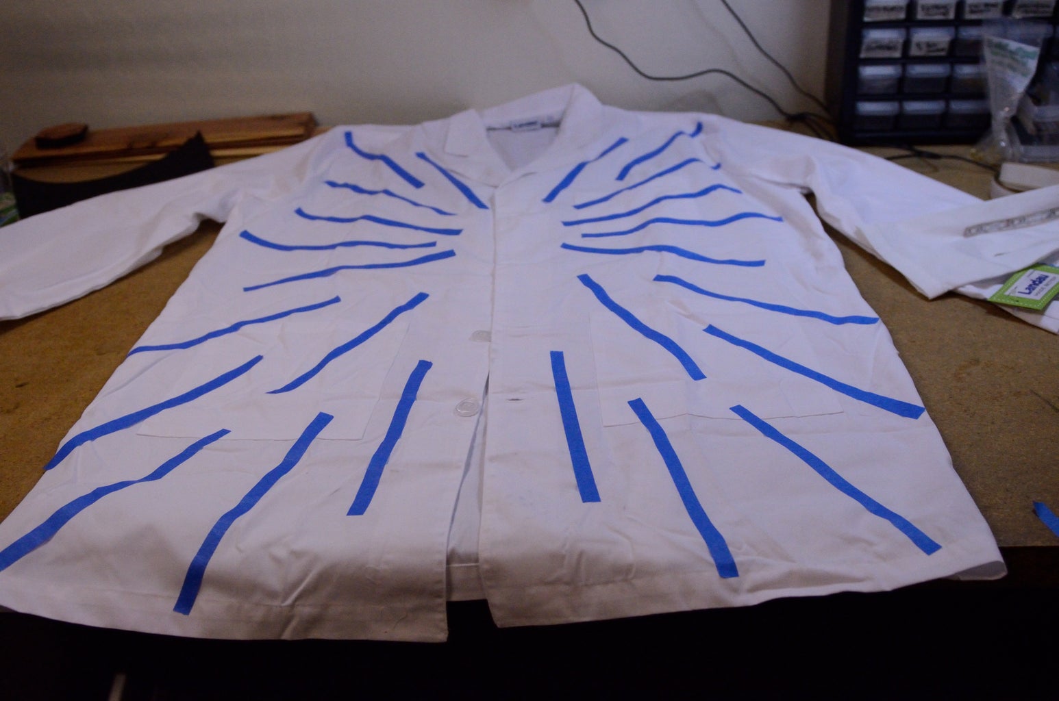

The coat, in summary, is one lab coat holding the lights in place while a second coat over it diffuses the light. At its heart, an Arduino takes in information from sensors and converts it to patterns of flashing colors. Easy enough, right? But before we can launch in, we need to answer a question of taste, first: What light-up pattern do you want?
We decided an a starburst pattern for Carl and Schuyler's coats. It's a dramatic look, and it makes the lights come together at one point, shortening the total amount of wire the coat has to carry. There's more than one right answer, though...
Once you've chosen your light pattern, take one of your two lab coats to lay out the pattern on. This will be the "undercoat" that holds the lights in place. Mark everywhere you want to put a light strip with masking tape. Note that your LED strips can only be cut at certain places (without breaking the circuit).
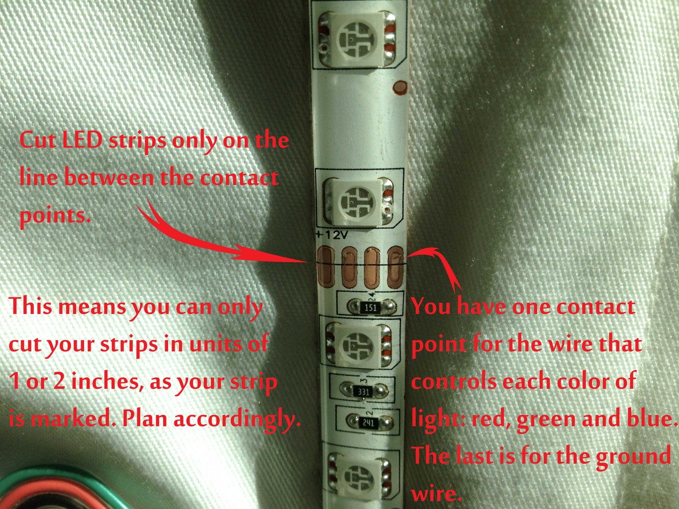
Step 2: Cut the Light Strips


Now, cut strips from your LED spool equal in length to each of the tape strips marking your undercoat. A sturdy pair of scissors will make short work of this. The cuts need to be on the lines between the contract points. Your strip may have contact points every inch, every two or three inches. Cut there, nowhere else.
After you've cut the LED strips, you need to cut the protective epoxy off the ends of the strips to expose the contact points you'll be soldering the wires down to.
Note: You might be tempted to skip this step by just buying the LED strips that have no epoxy coating. They're a little cheaper, and a little brighter, too. However, the epoxy is important for a couple reasons: First, it gives you a hint of weatherproofing. More importantly, it keeps the strips from getting any really hard kinks or bends as you move around in the coat. A hard kink in the LED strip repeated over and over will cause a stress break in the wires hidden within. That makes the strips go dark, usually one color at a time. (Ugly!) The epoxy prevents tight kinks in the wires, and the stress breaks they create.
Your LED strip has a tape-like adhesive on the back. (Typically.) Peel off the paper covering it to expose the sticky tape, and press the strip into place. This holds the strip on well enough to try on the coat and make sure the strips are sitting right. Yet it's weak enough you can peel the strips back off and move them if you need to.
The LED strips have a +12 volt side, printed by the cut edge. You wiring job will be much easier later if these are all stuck down with the +12 volt side pointing towards where you're going to power them from. For our starburst design, they all pointed to the center of the chest, where the power wires ran from.
Step 3: Bond the Light Strips to the Undercoat

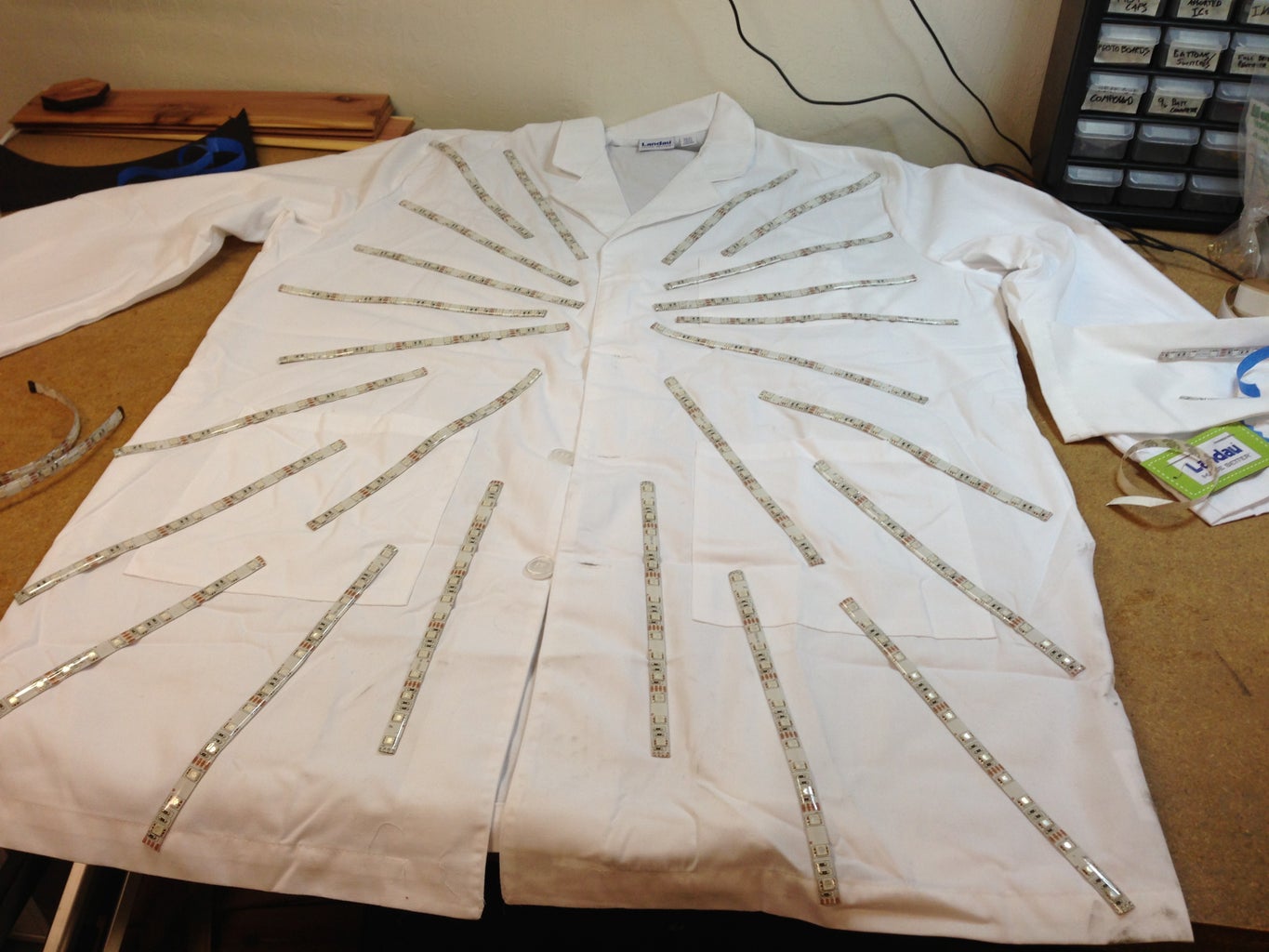
The LED rolls come with a peel-off glue layer, like tape. This is strong enough to stick them to a wall, but not enough to keep them hanging onto cloth that a person is moving in for hours. We're going to fix the strips with the salvation of the crafty: the hot glue gun.
Peel back each light strip, put a line of hot glue underneath, and press it back down.
- - - - - - - - - - - - - - - - - - - - - - - - - - - - - -
Note: If you didn't peel off the paper from the back of the strips to expose the sticky-tape in the previous step, you need to do it before applying your hot glue. Otherwise, you're glueing onto something that's meant to not stay attached, and only comedy can result from that.
Step 4: Wire-Up the Light Strips


Next up, cut a length of intercom wire long enough to run to a common point for each side. (We did this with four meeting points for the wire: front side left, front side right, back side left, back side right.) You're going to solder all these wires on to a common board to make wiring them back to the arduino later easier.
Next, get a six-pack of your favorite soda, tea, or coffee. Maybe two. You're about to start the longest part of the project: A few hundred careful solder joins.
Next, strip the wire ends, and carefully solder each of the four leads to the four contact pads on the LED strip. Repeat for each strip. Be consistent about which color wire connects to which pad. Take your time, and if the solder spills over onto a neighboring pad, carefully fix it.
All done? Congrats. That was the longest part of the project.
Next, we want a common point for the wires to join at. on each side(Front/Back; Left/Right). We cut small squares of protoboard, 4 pinholes wide (for each wire on a lead) and 20 rows long (with a row for each lead on the side, plus a bit of room to spare)
Each lead then gets soldered down to this hub mini-board. Each column of the mini-board has a wire soldered to each join on the back, so all the green wires can be lit from a single point of contact, all the red wires, etc..
Step 5: Sew the Coats Together
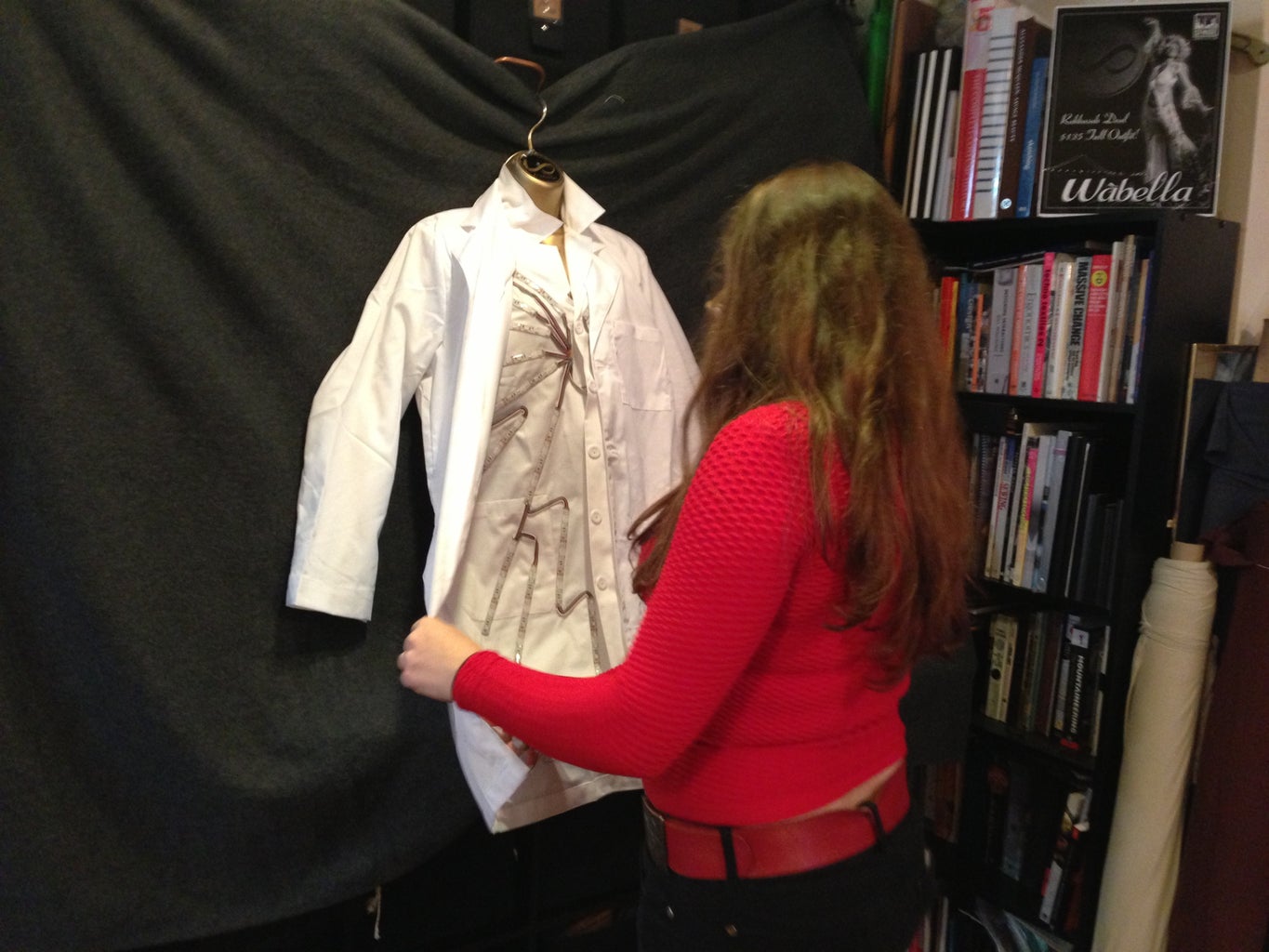

Now that you've got the undercoat wired, you're ready to sew it into the overcoat.
Sew the two coats together at the back of the shoulder, over the tops of the shoulders, and up the right and left sides. Leave gaps to run wires through at the armpits and midway up the flanks.
Cut off the collar of the outer coat. Add velcro joins to hold the outer coat to the inner coat at the collar.
To cut down on bulk, replace the button joins of the inner coat with a zipper; cut off the flap of fabric that the button holes lie in, and attach the zipper to one side. Remove the buttons from the other side and sew on the matching zipper.
Additional velcro strips can be added at the zipper line to hold the inner and outer coats together can be added, if desired.
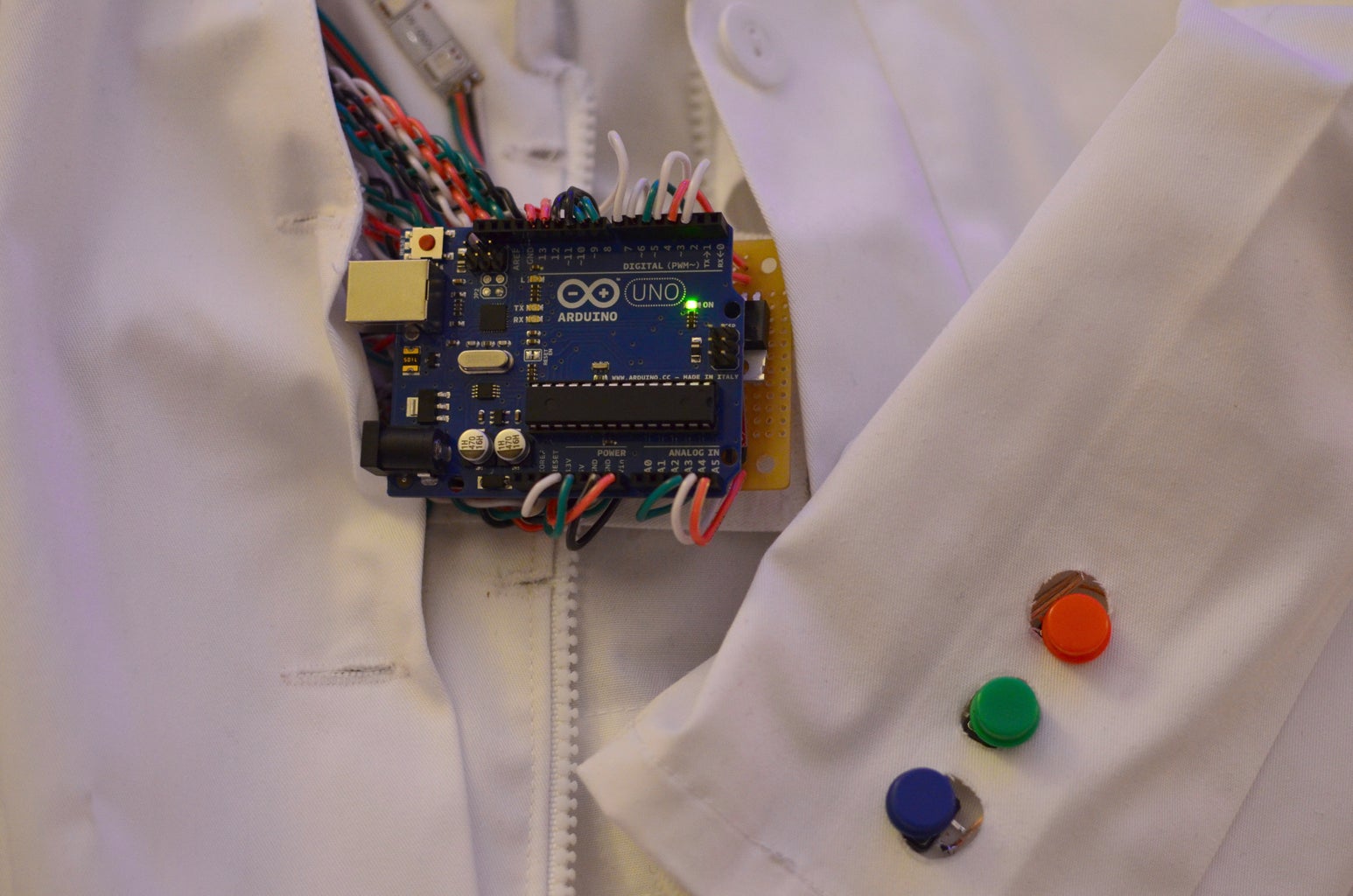
Sew any buttons you need into the sleeves: Sew them down to the undercoat and cut holes in the overcoat for them to pass through.
Step 6: Making the Transistor Board


See the picture above? We're going to make that now.
Don't worry. It's not half as complicated as it looks. Really, you're just soldering down 3 transistors (that's 9 solder points), one accelerometer (6 more solder points), and then tidying up the mess of wires you have on the coat by collecting them all here. It looks like a mess because this board is where all the different wiring strands from everyplace else come together. This is where you clean up.
- - - - - - - - - - - - - - - - - - - - - - - - - - - - - - - - -
The lights of the coat are driven off a transistor board: Even though we can power newer Arduinos directly off a 12-volt battery, we still can't pull the amperage needed to run yards of LED strips through the arduino without cooking it. So we route the three Arduino pins that drive the LEDs to a transistor each to control the battery->light strip power system.
The same way the Arduino can't handle that much amperage, an everyday 2N2222 transistor is going to cook if you try and run the light strips through it. We used "RFP30N06L MOSFET" transistors, which can handle the power and run cool while doing it.
- - - - - - - - - - - - - - - - - - - - - - - - - - - - - - - - -
This is also the time to run wires to the buttons and power. Pass the button wires down the sleeves to the buttons and connect them. The batteries rest in the pockets of the inner coat and are wired to the transistors. We used rechargeable 12 volt batteries, and cut one end off the barrel connector wires that came with them to get wires we could solder together (running the batteries in parallel) and then down to the board. 2 battery packs gave enough life to run Schuyler's coat for hours, 4 battery packs for Carl's coat.
- - - - - - - - - - - - - - - - - - - - - - - - - - - - - - - - -
We found it helpful to braid the larger wire bundles for power and signals. The visual distinction makes them easier to keep track of, and the braid offers a bit of strain absorption.
Step 7: Wiring to the Arduino


You're in the home stretch now. Now you just need take the connections you gathered on the previous board and run the wire for each to the arduino.
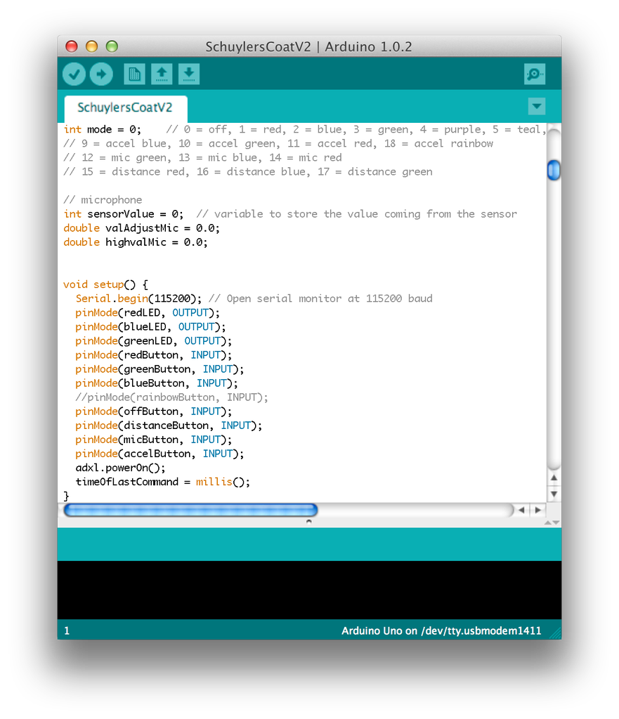
Step 8: Arduino Code
Your coat can light up in response to any number of sensors that can be wired to an Arduino. In the sample code you'll find an accelerometer (so it will flash as you walk and dance) a microphone (so it will flash as you talk) and a distance sensor (to glow brighter as things approach). But with all the different sensors you can plug into an Arduino, there's really no limit to what you could make your coat react to. You could plug in a temperature sensor to make your coat glow more red as you heat up. You could use a hall effect sensor to make a coat that glows to alert you of invisible magnetic fields. It's not like we've ever wired an alcohol sensor into one of these coats to turn a person into a glow-in-the-dark breathalizer. Except for that one time.
Point is, wiring new sensors into the arduino is the best way to make this coat your own. Get creative. Use the sample code below as a jumping off point, and get creative from there. Let us know in the comments what you rigged your coat to detect!
====================
The Code
====================
// included libraries
#include <Wire.h>
#include <ADXL345.h>
#include <NewPing.h>
// Sonar sensor
#define TRIGGER_PIN 11 // Arduino pin tied to trigger pin on the ultrasonic sensor.
#define ECHO_PIN 10 // Arduino pin tied to echo pin on the ultrasonic sensor.
#define MAX_DISTANCE 200 // Maximum distance we want to ping for (in centimeters). Maximum sensor distance is rated at 400-500cm.
NewPing sonar(TRIGGER_PIN, ECHO_PIN, MAX_DISTANCE); // NewPing setup of pins and maximum distance.
int power = 0;
int distance = 0;
// microphone sensor
int micPin = A3; // select the input pin for the potentiometer
// accel + accelRainbow + rainbow
double val = 0.0;
double valAdjustAccel = 0.0;
double highvalAccel = 0.0;
double maxVal = 0.0;
double blue, green, red;
double timecounter=0;
double tc = 200;
ADXL345 adxl; //variable adxl is an instance of the ADXL345 library
// PWM LEDs
int redLED = 5;
int blueLED = 6;
int greenLED = 3;
// buttons
int redButton = 7;
int greenButton = 4;
int blueButton = 2;
//int rainbowButton = 0;
int offButton = 8;
int distanceButton = 9;
int micButton = 12;
int accelButton = 13;
// other
int timer = 0;
// modes
int mode = 0; // 0 = off, 1 = red, 2 = blue, 3 = green, 4 = purple, 5 = teal, 6 = yellow, 7 = white, 8 = rainbow
// 9 = accel blue, 10 = accel green, 11 = accel red, 18 = accel rainbow
// 12 = mic green, 13 = mic blue, 14 = mic red
// 15 = distance red, 16 = distance blue, 17 = distance green
// microphone
int sensorValue = 0; // variable to store the value coming from the sensor
double valAdjustMic = 0.0;
double highvalMic = 0.0;
void setup() {
Serial.begin(115200); // Open serial monitor at 115200 baud
pinMode(redLED, OUTPUT);
pinMode(blueLED, OUTPUT);
pinMode(greenLED, OUTPUT);
pinMode(redButton, INPUT);
pinMode(greenButton, INPUT);
pinMode(blueButton, INPUT);
//pinMode(rainbowButton, INPUT);
pinMode(offButton, INPUT);
pinMode(distanceButton, INPUT);
pinMode(micButton, INPUT);
pinMode(accelButton, INPUT);
adxl.powerOn();
}
void loop() {
readColorButtons();
readAccelButton();
readMicButton();
readDistanceButton();
readOffButton();
// modes: 0 = off, 1 = red, 2 = blue, 3 = green, 4 = purple, 5 = teal, 6 = yellow, 7 = white, 8 = rainbow
// 9 = accel blue, 10 = accel green, 11 = accel red, 18 = accel rainbow
// 12 = mic green, 13 = mic blue, 14 = mic red
// 15 = distance red, 16 = distance blue, 17 = distance green
if (mode == 0)// off
{
digitalWrite(redLED, LOW);
digitalWrite(greenLED, LOW);
digitalWrite(blueLED, LOW);
}
if (mode == 1) //red
{
digitalWrite(redLED, HIGH);
digitalWrite(greenLED, LOW);
digitalWrite(blueLED, LOW);
}
if (mode == 2) //blue
{
digitalWrite(redLED, LOW);
digitalWrite(greenLED, LOW);
digitalWrite(blueLED, HIGH);
}
if (mode == 3) // green
{
digitalWrite(redLED, LOW);
digitalWrite(greenLED, HIGH);
digitalWrite(blueLED, LOW);
}
if (mode == 4) // purple
{
digitalWrite(redLED, HIGH);
digitalWrite(greenLED, LOW);
analogWrite(blueLED, 50);
}
if (mode == 5) // teal
{
digitalWrite(redLED, LOW);
digitalWrite(greenLED, HIGH);
analogWrite(blueLED, 50);
}
if (mode == 6) // yellow
{
digitalWrite(redLED, HIGH);
digitalWrite(greenLED, HIGH);
digitalWrite(blueLED, LOW);
}
if (mode == 7) // white
{
digitalWrite(redLED, HIGH);
digitalWrite(greenLED, HIGH);
digitalWrite(blueLED, HIGH);
}
if (mode == 8) // rainbow
{
rainbow();
}
if (mode == 9 || mode == 10 || mode == 11) // accel blue, green, red
{
accel();
}
if (mode == 12 || mode == 13 || mode == 14) // mic green, blue, red
{
mic();
}
if (mode == 15 || mode == 16 || mode == 17) // distance red, blue, green
{
distanceSensor();
}
if (mode == 18) // accel rainbow
{
accelRainbow();
}
}
void mic() {
// read the value from the sensor:
sensorValue = analogRead(micPin);
Serial.println(highvalMic);
valAdjustMic=sensorValue-390;
if (valAdjustMic > highvalMic)
{
highvalMic = valAdjustMic;
}
else
{
highvalMic = highvalMic*.90;
}
// if (highvalMic > maxVal)
// {
// maxVal = highvalMic;
// }
if(highvalMic < 100)
{
highvalMic=0;
}
if (mode==14)
{
analogWrite(greenLED,highvalMic);
digitalWrite(blueLED, LOW);
digitalWrite(redLED, LOW);
}
if (mode==13)
{
analogWrite(blueLED,highvalMic);
digitalWrite(redLED, LOW);
digitalWrite(greenLED, LOW);
}
if (mode==12)
{
analogWrite(redLED,highvalMic);
digitalWrite(blueLED, LOW);
digitalWrite(greenLED, LOW);
}
delay(1);
}
void distanceSensor() {
delay(50); // Wait 50ms between pings (about 20 pings/sec). 29ms should be the shortest delay between pings.
unsigned int uS = sonar.ping(); // Send ping, get ping time in microseconds (uS).
distance = uS / US_ROUNDTRIP_CM;
Serial.print("Ping: ");
Serial.print(uS / US_ROUNDTRIP_CM); // Convert ping time to distance in cm and print result (0 = outside set distance range)
Serial.println("cm");
if (distance > 29 && distance < 131)
{
power = (distance - 30)*2.55;
}
if (distance < 30 || distance > 150)
{
power = 0;
}
if (distance > 130)
{
power = 255;
}
if (mode==17)
{
analogWrite(greenLED,power);
digitalWrite(blueLED, LOW);
digitalWrite(redLED, LOW);
}
if (mode==16)
{
analogWrite(blueLED,power);
digitalWrite(greenLED, LOW);
digitalWrite(redLED, LOW);
}
if (mode==15)
{
analogWrite(redLED,power);
digitalWrite(blueLED, LOW);
digitalWrite(greenLED, LOW);
}
}
void accel() {
//Boring accelerometer stuff
int x,y,z;
adxl.readAccel(&x, &y, &z); //read the accelerometer values and store them in variables x,y,z
double dx, dy, dz;
dx = (double)abs(x)/100;
dy = (double)abs(y)/100;
dz = (double)abs(z)/100;
val = sqrt((dx*dx)+(dy*dy)+(dz*dz));
//val = sqrt((x*x)+(y*y)+(z*z));
// Output x,y,z values - Commented out
//Serial.print(val);
valAdjustAccel=val-3;
if (valAdjustAccel > highvalAccel)
{
highvalAccel = valAdjustAccel;
}
else
{
highvalAccel = highvalAccel*.83;
}
// if (highvalAccel > maxVal)
// {
// maxVal = highvalAccel;
// }
if(highvalAccel*57 < 4)
{
highvalAccel=4/57;
}
if (mode == 10)
{
blue = 1;
red = 0;
green = 0;
}
if (mode == 9)
{
blue = 0;
red = 0;
green = 1;
}
if (mode == 11)
{
blue = 0;
red = 1;
green = 0;
}
analogWrite(blueLED,highvalAccel*57*blue);
analogWrite(greenLED,highvalAccel*57*green);
analogWrite(redLED,highvalAccel*57*red);
delay(30);
}
void accelRainbow() {
//Boring accelerometer stuff
int x,y,z;
adxl.readAccel(&x, &y, &z); //read the accelerometer values and store them in variables x,y,z
double dx, dy, dz;
dx = (double)abs(x)/100;
dy = (double)abs(y)/100;
dz = (double)abs(z)/100;
val = sqrt((dx*dx)+(dy*dy)+(dz*dz));
//val = sqrt((x*x)+(y*y)+(z*z));
// Output x,y,z values - Commented out
//Serial.print(val);
valAdjustAccel=val-3;
if (valAdjustAccel > highvalAccel)
{
highvalAccel = valAdjustAccel;
}
else
{
highvalAccel = highvalAccel*.83;
}
// if (highvalAccel > maxVal)
// {
// maxVal = highvalAccel;
// }
if(highvalAccel*57 < 4)
{
highvalAccel=4/57;
}
analogWrite(blueLED,highvalAccel*57*blue);
analogWrite(greenLED,highvalAccel*57*green);
analogWrite(redLED,highvalAccel*57*red);
delay(30);
timecounter = timecounter + 30;
if (timecounter<tc)
{
red = 1;
blue = 0 + (timecounter)/tc;
}
if (timecounter > 2*tc && timecounter < 3*tc)
{
red = 1 - (timecounter-2*tc)/tc;
}
if (timecounter > 4*tc && timecounter < 5*tc)
{
green= 0 + (timecounter-4*tc)/tc;
}
if (timecounter > 6*tc && timecounter < 7*tc)
{
blue= 1 - (timecounter-6*tc)/tc;
}
if (timecounter > 8*tc && timecounter < 9*tc)
{
red=0 + (timecounter-8*tc)/tc;
}
if (timecounter > 10*tc && timecounter < 11*tc)
{
green=1-(timecounter-10*tc)/tc;
}
if (timecounter > 12*tc)
{
timecounter = 0;
}
Serial.print(red);
Serial.print(" ");
Serial.print(blue);
Serial.print(" ");
Serial.print(green);
Serial.print(" ");
Serial.println(timecounter);
}
void rainbow() {
analogWrite(blueLED,255*blue);
analogWrite(greenLED,255*green);
analogWrite(redLED,255*red);
delay(30);
timecounter = timecounter + 30;
if (timecounter<tc)
{
red = 1;
blue = 0 + (timecounter)/tc;
}
if (timecounter > 2*tc && timecounter < 3*tc)
{
red = 1 - (timecounter-2*tc)/tc;
}
if (timecounter > 4*tc && timecounter < 5*tc)
{
green= 0 + (timecounter-4*tc)/tc;
}
if (timecounter > 6*tc && timecounter < 7*tc)
{
blue= 1 - (timecounter-6*tc)/tc;
}
if (timecounter > 8*tc && timecounter < 9*tc)
{
red=0 + (timecounter-8*tc)/tc;
}
if (timecounter > 10*tc && timecounter < 11*tc)
{
green=1-(timecounter-10*tc)/tc;
}
if (timecounter > 12*tc)
{
timecounter = 0;
}
Serial.print(red);
Serial.print(" ");
Serial.print(blue);
Serial.print(" ");
Serial.print(green);
Serial.print(" ");
Serial.println(timecounter);
}
void readColorButtons() {
if (digitalRead(redButton)==HIGH && digitalRead(greenButton)==LOW && digitalRead(blueButton)==LOW)
{
mode = 1; // red
timer = 0;
}
if (digitalRead(redButton)==LOW && digitalRead(greenButton)==LOW && digitalRead(blueButton)==HIGH)
{
mode = 2; // blue
timer = 0;
}
if (digitalRead(redButton)==LOW && digitalRead(greenButton)==HIGH && digitalRead(blueButton)==LOW)
{
mode = 3; // green
timer = 0;
}
if (digitalRead(redButton)==HIGH && digitalRead(greenButton)==LOW && digitalRead(blueButton)==HIGH)
{
mode = 4; // purple
digitalWrite(redLED, HIGH);
digitalWrite(greenLED, LOW);
analogWrite(blueLED, 50);
delay (250);
timer = 0;
}
if (digitalRead(redButton)==LOW && digitalRead(greenButton)==HIGH && digitalRead(blueButton)==HIGH)
{
mode = 5; // teal
digitalWrite(redLED, LOW);
digitalWrite(greenLED, HIGH);
analogWrite(blueLED, 50);
delay (250);
timer = 0;
}
if (digitalRead(redButton)==HIGH && digitalRead(greenButton)==HIGH && digitalRead(blueButton)==LOW)
{
mode = 6; // yellow
digitalWrite(redLED, HIGH);
digitalWrite(greenLED, HIGH);
digitalWrite(blueLED, LOW);
delay(250);
timer = 0;
}
if (digitalRead(redButton)==HIGH && digitalRead(greenButton)==HIGH && digitalRead(blueButton)==HIGH)
{
mode = 8; // rainbow
digitalWrite(redLED,LOW);
digitalWrite(blueLED,LOW);
digitalWrite(greenLED,LOW);
delay (250);
timer = timer + 250;
}
// if (timer == 1500)
// {
// mode = 8; // rainbow colors
// digitalWrite(redLED, LOW);
// digitalWrite(blueLED, LOW);
// digitalWrite(greenLED, LOW);
// delay (500);
// timer = 0;
// }
// if (timer == 3000);
// {
// mode = 0;
// digitalWrite(redLED, LOW);
// digitalWrite(blueLED, HIGH);
// digitalWrite(greenLED, LOW);
// delay(500);
// digitalWrite(redLED, LOW);
// digitalWrite(blueLED, LOW);
// digitalWrite(greenLED, HIGH;
// delay(500);
// digitalWrite(redLED, HIGH);
// digitalWrite(blueLED, LOW);
// digitalWrite(greenLED, LOW);
// delay(500);
// digitalWrite(redLED, LOW);
// digitalWrite(blueLED, LOW);
// digitalWrite(greenLED, LOW);
// timer = 0;
// }
//
}
void readAccelButton() {
if (digitalRead(accelButton)) // 9 = accel blue, 10 = accel green, 11 = accel red, 18 = accel rainbow
{
if (mode==9) // already accel blue
{
mode=10; // make accel green
delay(500);
}
else if (mode==10) // already accel green
{
mode=11; // make accel red
delay(500);
}
else if (mode==11) // already accel red
{
mode=18; // make accel rainbow
delay(500);
}
else if (mode==18) // already accel rainbow
{
mode=9; // make accel blue
delay(500);
}
else
{
mode = 9; // make accel blue
delay(500);
}
}
}
void readMicButton() {
if (digitalRead(micButton)) // 12 = mic green, 13 = mic blue, 14 = mic red
{
if (mode==12) // already mic green
{
mode=13; // make mic blue
delay(500);
}
else if (mode==13) // already mic blue
{
mode=14; // make mic red
delay(500);
}
else if (mode==14) // already mic red
{
mode=12; // make mic green
delay(500);
}
else
{
mode = 12; // make mic green
delay(500);
}
}
}
void readDistanceButton() {
if (digitalRead(distanceButton)) // 15 = distance red, 16 = distance blue, 17 = distance green
{
if (mode==15) // already distance red
{
mode=16; // make distance blue
delay(500);
}
else if (mode==16) // already distance blue
{
mode=17; // make distance green
delay(500);
}
else if (mode==17) // already distance green
{
mode=15; // make distance red
delay(500);
}
else
{
mode = 15; // make distance red
delay(500);
}
}
}
void readOffButton() {
if (digitalRead(offButton))
{
mode = 0;
}
}
Step 9: Re-Test the Connections

Your coat has a LOT of solder points, and a LOT of wires jumpered onto the Arduino. In a moment you're going to seal up the remaining loose points. Before you do, now is a good time to fire up each color and mode and make sure all your solders are holding.
Step 10: Glue Down the Cuffs

Hot glue the cuffs together, securing the inner coat to the outer coat.
Roll back the overcoat sleeve from the undercoat. Add a dot of hot glue to the inner coat between each button on the undercoat, then roll the overcoat sleeve back on top, getting the buttons through the holes, and press down.
Next a strip of glue around the outermost section of the cuff of the undercoat, and press the overcoat onto that.
Repeat for the second sleeve.
Step 11: Go Be Awesome


You've got a light-up coat! Go forth, be awesome. Now that you've got a garment that reacts to the world around it, try plugging new sensors into the arduino and tweaking the code. What else can you make it do?

Participated in the
Make It Glow

Participated in the
Instructables Design Competition


