

Introduction: Interfacing SIM900A GSM Modem With Arduino


This is a very low cost and simple Arduino GSM and GPRS module. We use the module SIMCom SIM900A . It’s the cheaper module now avalaible in the market.This post will allow you to make arduino controlled calls and also send text messages.
Step 1: Some Important Notes and Powering Up the GSM Module
1. We use SIM900 GSM Module – This means the module supports communication in 900MHz band. We are from India and most of the mobile network providers in this country operate in the 900Mhz band. If you are from another country, you have to check the mobile network band in your area. A majority of United States mobile networks operate in 850Mhz band (the band is either 850Mhz or 1900Mhz). Canada operates primarily on 1900 Mhz band.
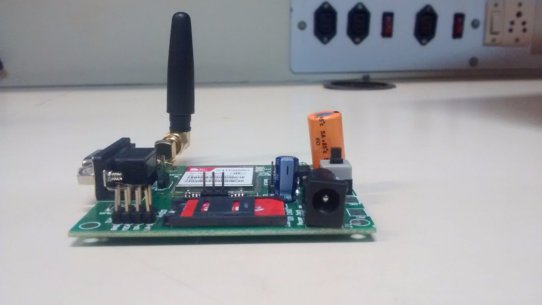
2. Check the power requirements of GSM module – GSM modules are manufactured by different companies. They all have different input power supply specs. You need to double check your GSM modules power requirements. In this tutorial, our gsm module requires a 12 volts input. So we feed it using a 12V,1A DC power supply. I have seen gsm modules which require 15 volts and some other which needs only 5 volts. They differ with manufacturers. If you are having a 5V module, you can power it directly from Arduino’s 5V out.
BOOTING UP THE GSM:
1. Insert the SIM card to module and lock it.
2. Connect the adapter to module and turn it ON!
3. Now wait for some time (say 1 minute) and see the blinking rate of ‘status LED’ (GSM module will take some time to establish connection with mobile network)
4. Once the connection is established successfully, the status LED will blink continuously every 3 seconds.
Step 2: Making Connections

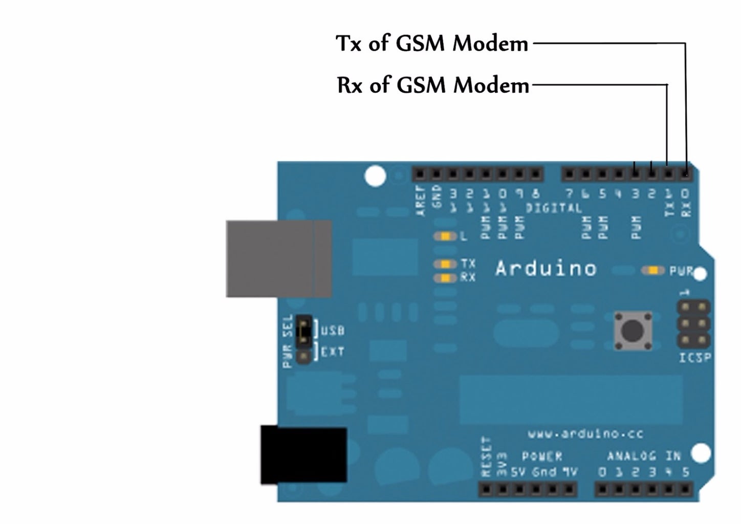
There are two ways of connecting GSM module to arduino. In any case, the communication between Arduino and GSM module is serial. So we are supposed to use serial pins of Arduino (Rx and Tx). So if you are going with this method, you may connect the Tx pin of GSM module to Rx pin of Arduino and Rx pin of GSM module to Tx pin of Arduino.
Now connect the ground pin of arduino to ground pin of gsm module! So that’s all! You made 3 connections and the wiring is over! Now you can load different programs to communicate with gsm module and make it work.
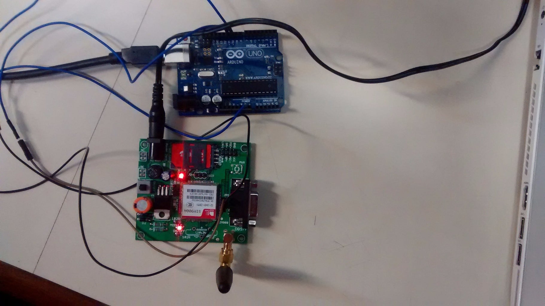
Note:- The problem with this connection is while programming. Arduino uses serial ports to load program from the Arduino IDE. If these pins are used in wiring, the program will not be loaded successfully to Arduino. So you have to disconnect wiring in Rx and Tx each time you burn the program. Once the program is loaded successfully, you can reconnect these pins and have the system working! To avoid this difficulty, I am using an alternate method in which two digital pins of arduino are used for serial communication. We need to select two PWM enabled pins of arduino for this method. So I choose pins 9 and 10 (which are PWM enabled pins). This method is made possible with theSoftwareSerial Library of Ardunio. SoftwareSerial is a library of Arduino which enables serial data communication through other digital pins of Arduino. The library replicates hardware functions and handles the task of serial communication.
Step 3: The Code: Calling and Messaging


