

Introduction: Intermediate Arduino: Inputs and Outputs


Continuing from my Intro to Arduino post, this Instructable will go over some slightly more advanced topics with Arduino, specifically relating to controlling and managing many inputs and outputs. The next class covers how to connect the Arduino's inputs and outputs to MIDI.
Parts List:
(1x) Arduino Uno Amazon or you can pick one up at a local Radioshack
(1x) usb cable Amazon
(1x) breadboard (this one comes with jumper wires) Amazon
(1x) jumper wires Amazon
(8x) red LEDs Digikey C503B-RCN-CW0Z0AA1-ND
(8x) 220Ohm resistors Digikey CF14JT220RCT-ND
(1x) 10kOhm resistor Digikey CF14JT10K0CT-ND
(1x) tact button Digikey 450-1650-ND
(1x) 595 shift register Digikey 296-1600-5-ND
(1x) red LED dot matrix Adafruit 454
Step 1: Blink Without Delay()
So far we've been using the delay() function to pause the Arduino sketch momentarily so that a little time can pass between two Arduino commands. In the LED blink sketch, we used delay() to set the amount of time the Arduino was lit and the amount of time it was turned off:
digitalWrite(ledPin, HIGH);//turn LED on
delay(1000);// wait for 1000 milliseconds (one second)
digitalWrite(ledPin, LOW);//turn LED off
delay(1000);//wait one second
Sometimes using delay() is not a great option because the Arduino can't perform any secondary tasks while the delay is happening. Imagine we wanted to blink an LED and detect a button press at the same time using delay():
loop(){
digitalWrite(ledPin, HIGH);
delay(1000);
digitalWrite(ledPin, LOW);
delay(1000);
boolean buttonState = digitalRead(7);
}
In the code above, we are only measuring the button once every two seconds, so it may take up to two seconds before a button press is detected, and very brief presses might not ever get detected at all.
millis() gives us control over when events happen without putting pauses in the sketch. Each time we call millis() in an Arduino sketch, it returns the number of milliseconds since the Arduino was turned on.
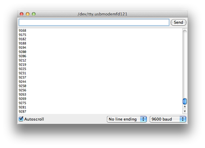
Run the following code to see how millis() works:
//recording time with Arduino millis()

void setup() {
  Serial.begin(9600);
}

void loop()
{
  unsigned long currentMillis = millis();
  Serial.println(currentMillis);
}
Here's how to use millis() to blink an LED without using delay().
//blink led without delay()

int ledPin =  7;

int ledState = LOW;//current state of the LED
unsigned long timeOfLastLedEvent = 0;//the last time the LED was updated

int intervalON = 1000;//how long we want the LED to stay on
int intervalOFF = 500;//how long we want the LED to stay off

void setup() {
  pinMode(ledPin, OUTPUT);
  digitalWrite(ledPin, ledState);
}

void loop() {

  unsigned long currentMillis = millis();

  if (ledState == LOW){//if the LED is already off
    if (currentMillis - timeOfLastLedEvent > intervalOFF){//and enough time has passed
      digitalWrite(ledPin, HIGH);//turn it on
      ledState = HIGH;//store its current state
      timeOfLastLedEvent = currentMillis;//update the time of this new event
    }
  } else {//if the LED is already on
    if (currentMillis - timeOfLastLedEvent > intervalON){
      digitalWrite(ledPin, LOW);
      ledState = LOW;
      timeOfLastLedEvent = currentMillis;
    }
  }
}
The sketch above introduces a few new things:
unsigned long is another data type (so far we've seen int and boolean). Unsigned long is like int, but larger, I'll explain... Each data type requires a certain amount of space in the Arduino's memory, and the amount of space that the Arduino frees up for a given variable dictates the min and max values that the variable can store. For example, int's can range from -32,768 to 32,767, if you tried to do something like this:
int myVariable = 100,000;
You would end up with a very strange bug in your code. This may seem like an arbitrary range, but it comes from the fact that int's require 16 bits of space in the Arduino's memory, and with 16 bits of binary you can store numbers from 0 to (2^16-1) = 65535. But people decided that int should be able to store negative numbers too, so one of the bits in the 16 bit number is used to store the sign (positive or negative) and the remaining 15 bits store the value : 2^15 = 32768. Including 0, we end up with the range -32,768 to 32,767. Another data type called an insigned int does not store sign, so it gets the 0 to 65535 range that I calculated before, but you cannot store a negative number in an insigned int.
When we need to use numbers larger than 65535 or less than -32768, we use a data type called long. Long is allocated 32 bits of space in the Arduino's memory. 2^32 = 4,294,967,296, center this around zero to get a range of : -2,147,483,648 to 2,147,483,647. Unsigned long's, like unsigned int's are always positive, so they range from 0 to 4,294,967,295.
There is no larger data type for storing numbers than long, so if you need to store a number larger than 4,294,967,295, you'll have to come up with a different way to store it (maybe the first 9 bits in one number and the last nine in another?). This limitation has some interesting consequences for the millis() function. Since millis returns unsigned longs, and it's constantly counting up in milliseconds, millis() will actually reset back to zero once it reaches:
4,294,967,295 ms
= 4,294,967seconds
= 49.71 days
If you use millis() and you plan on keeping you project running for extended periods of time without ever turning it off or resetting, you should be mindful of this.
One more comment about data types: We could have been using long's or unsigned long's this whole time when we declare pin numbers or other variables in the example sketches so far, but generally it's a good idea to use the smallest data type possible for a variable, that way you have plenty of extra space in the Arduino's memory for other things. In Arduino, longs are rarely used, but millis() is a good example of when they come in handy.
Getting back to the sketch, the general idea is to store the last time you toggled the LED on or off and compare that with the current time returned by millis(). Once the difference between those two times is greater than some interval, you know it's time to toggle the LED again. To do this I've set up some new storage variables:
int ledState = LOW;//current state of the LED
unsigned long timeOfLastLedEvent = 0;//the last time the LED was updated
int intervalON = 1000;//how long we want the LED to stay on
int intervalOFF = 500;//how long we want the LED to stay off
In the loop() there's a bunch of logic that checks to see if enough time has passed, and if so, toggles the LED, updates the variable "timeOfLastLedEvent", and toggles the stored state of the LED. The logic is repeated twice, once for the case that the LED is HIGH, and once for the case that the LED is low, I'll repeat the LOW case below:
if (currentMillis - timeOfLastLedEvent > intervalOFF){//and enough time has passed
digitalWrite(ledPin, HIGH);//turn it on
ledState = HIGH;//store its current state
timeOfLastLedEvent = currentMillis;//update the time of this new event
}
currentMillis is an unsigned long representing the current time that is updated each time the Arduino's loop() function starts. (currentMillis - timeOfLastLedEvent) gives the time sine the LED's state was last changed, we compare this against the intervalOFF to see if it's time to turn off the LED, if it's not the Arduino will keep updating currentMillis and re-checking until it's time.
Step 2: Arduino Button Debouncing
Continuing from the button debouncing I introduced in my last Instructable, we can use millis() to debounce buttons without using delay():
//Button Press Detection - debounce with millis()

int buttonPin = 7;

boolean currentState = LOW;//stroage for current measured button state
boolean lastState = LOW;//storage for last measured button state
boolean debouncedState = LOW;//debounced button state

int debounceInterval = 20;//wait 20 ms for button pin to settle
unsigned long timeOfLastButtonEvent = 0;//store the last time the button state changed

void setup(){
  pinMode(buttonPin, INPUT);//this time we will set the pin as INPUT
  Serial.begin(9600);//initialize Serial connection
}

void loop(){

  currentState = digitalRead(buttonPin);
  unsigned long currentTime = millis();

  if (currentState != lastState){
    timeOfLastButtonEvent = currentTime;
  }

  if (currentTime - timeOfLastButtonEvent > debounceInterval){//if enough time has passed
    if (currentState != debouncedState){//if the current state is still different than our last stored debounced state
      debouncedState = currentState;//update the debounced state

      //trigger an event
      if (debouncedState == HIGH){
        Serial.println("pressed");
      } else {
        Serial.println("released");
      }
    }
  }

  lastState = currentState;
}
In this code, I've added some new storage variables:
boolean debouncedState = LOW;
int debounceInterval = 20;
unsigned long timeOfLastButtonEvent = 0;
debouncedState stores the current debounced state of the button, this is the state we are absolutely sure the button is in. By contrast, currentState and lastState store the current and last measurements we made of the button, but they do not tell us the state of the button with certainty because they may be affected by button chatter.
debounceInterval is the amount of ms to wait for the button pin to settle before we know for sure what state it is in. I'm my last example I'd been using 1ms, here I'm using 20ms.
timeOfLastButtonEvent is similar to timeOfLastLedEvent in the last sketch, it gives a time to compare with currentTime so that we can count how many seconds have passed since first detecting a button press.
We reset timeOfLastButtonEvent each time currentState does not equal lastState:
if (currentState != lastState){
timeOfLastButtonEvent = currentTime;
}
Once enough time has passed without needing to reset timeOfLastButtonEvent, we know the button has settled into a debounced state:
currentTime - timeOfLastButtonEvent > debounceInterval
Then we can update the current stored debounce state if it has changed, and if so, trigger an event according to the new debounce state:
if (currentState != debouncedState){
debouncedState = currentState;
if (debouncedState == HIGH){
Serial.println("pressed");
} else {
Serial.println("released");
}
}
Step 3: Shift Registers
So far we've seen how we can use the Arduino to control many digital inputs and outputs at once, but sometimes we will want to control more components than the Arduino has pins for. In this case, we can use an external integrated circuit (also called a "chip") to expand the Arduino's inputs and outputs.
Shift registers are chips which use logic gates to control many inputs or outputs at once. They are inherently digital, like the digital pins on the Arduino - this means that they can only read or write 0V and 5V (LOW or HIGH). If you are looking for something to expand your analog inputs then you'll want a demultiplexer like the 4051 (read more about how to use that here). In this Instructable we'll be looking at the 74HC595 shift register (called the "595"), it's very popular because it can expand 3 Arduino digital outputs into 8 outputs.
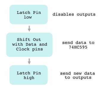
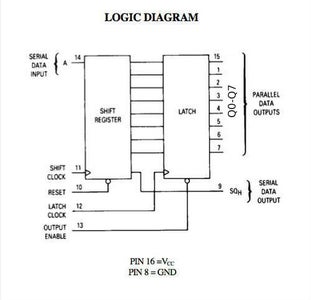
The 595 has 8 output pins labeled Q0-Q7 (sometimes also called Qa-Qh), it cannot read data from these pins, they can only be used as outputs (if you are looking for a shift register with 8 input pins, check out the 74HC165, tutorial here). The 595 is controlled by three connections, they are called the data pin, latch pin, and clock pin. Refer to the flow diagram above to see how to control the output pins (repeated below):
- first, the latch pin (labeled "latch clock" in the second diagram above) is set LOW to disable the output pins (labeled "parallel data outputs"), this way the output pins won't change as we are sending in new data to the 595
- next, new data is sent to the 595 by pulsing the clock pin("shift clock") and sending each of 8 output states through the data pin("serial data input") one by one. Arduino has a handy function in its library called shiftOut that takes care of this for you, I'll explain how to use this in the next step.
- finally, set the latch pin HIGH. This sends your new data to all the output pins at once (called parallel output).
Step 4: 595 and ShiftOut


Next we'll take a look at the 595's data sheet to find the right pins to connect to. This first image above shows the 595 pin connections. There are 16 pins on the 595, labelled 1-16. Notice the half circle marking on one side of the chip, the #1 pin is always located on the left side of this chip. The rest of the pins are numbered around the chip going in the counterclockwise direction.
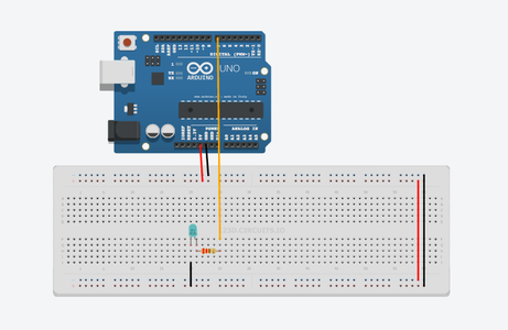
The second image shows the pin name, ordered by pin number, with a short description. Pins 1-7 and 15 are the outputs Q0-Q7, leave those pins unconnected for now. Pin 8 is a ground pin, connect this to Arduino ground. Pin 9 is a serial data output, this is used to connect to other 595's for daisy chaining. Daisy chaining allows you to drive 16 or more outputs using just three of the Arduino's digital pins. It is a bit outside the scope of this tutorial, but you can read more about it here. Since we will not use pin 9, we can leave it unconnected (also called "floating"). Pin 10 is the master reset, when this pin goes LOW, it causes the shift register to reset - losing any data we might have stored previously. We do not want this functionality right now, so connect the reset to 5V to prevent resetting from happening. Pin 11 is the clock input or "clock pin", connect this to Arduino digital pin 7. Pin 12 is the storage register clock input or "latch pin", connect this to Arduino digital pin 6. Pin 13 is the output enable pin, when it is LOW it allows the 595 to send data to its outputs, we want this, connect this pin to ground. Pin 14 is the serial data input, connect this to Arduino digital pin 5. Pin 16 is the power supply to the chip, connect this to 5V. Your circuit should look like image 3.
Now connect an LED and a resistor to ground to each of the 595's eight outputs pins. Your circuit should now look like image 4. Now setting an output pin of the 595 HIGH will turn on the corresponding LED, and setting it LOW will turn the LED off. Upload the following code:
//set 595 state

int clockPin = 7;
int latchPin = 6;
int dataPin = 5;

byte numberToDisplay = 154;


void setup() {
  //all connections to 595 are outputs
  pinMode(latchPin, OUTPUT);
  pinMode(clockPin, OUTPUT);
  pinMode(dataPin, OUTPUT);
}

void loop() {
    //first set latch pin low so we can shift in data without disrupting the outputs
    digitalWrite(latchPin, LOW);
    // shift out bits of data
    shiftOut(dataPin, clockPin, LSBFIRST, numberToDisplay);
    //set latch pin high to send data to output pins
    digitalWrite(latchPin, HIGH);
}
This code introduces a new data type called byte, byte is like int, but since bytes only require 8 bits of memory, they only store numbers between 0 and 255 (2^8 = 256).
The rest of the code is straightforward, except for the line:
shiftOut(dataPin, clockPin, LSBFIRST, numberToDisplay);
In this line, the Arduino uses the data and clock pins of the 595 to send the number 154 (the current value of numberToDisplay) into the shift register. The number 154 contains the states of all 8 pins of the 595:
154 converted to binary is 10011010
If you look at the states of your LEDs, you'll see that the LED connected to Q0 is on, Q1 and Q2 are off, Q3 and Q4 are on, Q5 is off, Q6 is on, and Q7 is off. So the LEDs follow the same pattern as the binary number, a 1 represents an on LED and a 0 represents an off LED.
Now try other numbers, the number 15 is binary is 00001111, you can find other decimal to binary conversions on google by typing a # then the phrase "to binary" (the number it spits out will start with 0b, ignore that part and grab the last 8 digits). Remember that we can only send binary numbers with 8 digits in them (8-bit) to the shift register because it only has 8 output pins, so the value of numberToDisplay must be between 0 and 255.
Now try changing the parameter LSBFIRST to MSBFIRST, you should see the order of the LEDs reverse, this variable sets the direction that we send the binary number into the 595: LSBFIRST means "least significant bit first" and MSBFIRST means "most significant bit first".
To make it a little more interesting, try the following:
int clockPin = 7;
int latchPin = 6;
int dataPin = 5;


void setup() {
  //all connections to 595 are outputs
  pinMode(latchPin, OUTPUT);
  pinMode(clockPin, OUTPUT);
  pinMode(dataPin, OUTPUT);
}

void loop() {
  for (byte numberToDisplay=0;numberToDisplay<256; numberToDisplay++){
    digitalWrite(latchPin, LOW);
    // shift out bits of data
    shiftOut(dataPin, clockPin, MSBFIRST, numberToDisplay);
    //set latch pin high to send data to output pins
    digitalWrite(latchPin, HIGH);

    delay(500);
  }
}
Now you've turned your LEDs into a binary counter:
Step 5: Arduino Controlled LED Matrix
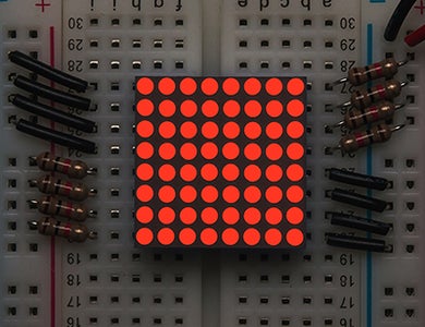


Next we'll look at using Arduino to control an 8x8 LED matrix, a grid of 64 LEDs. The 8x8 matrix we'll be using has 16 pin connections to it: eight pins connect the positive leads of all the LEDs in each column of the matrix, and eight more pins connect the ground leads of all the LEDs in each row of the matrix. This gives us control to adress each LED individually. Look at the diagram in the second image above. Image that all columns are grounded except column 8, which is connected (through a current limiting resistor) to 5V. No image that all rows are connected to 5V except row 1, which is connected to ground. The only LED that will light up in this scenario is located in row 1 and column 1.
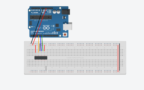
Place the LED matrix in a breadboard as shown in the first image. Use a current limiting resistor to connect the columns (see pin numbering in the second image) to 5V and use a regular jumper wire to connect the rows to ground. You should see the entire LED display light up. Now try unplugging a row from ground and connecting it to 5V instead, every LED in that row will turn off. Try connecting a column to ground, every LED in that column will turn off.
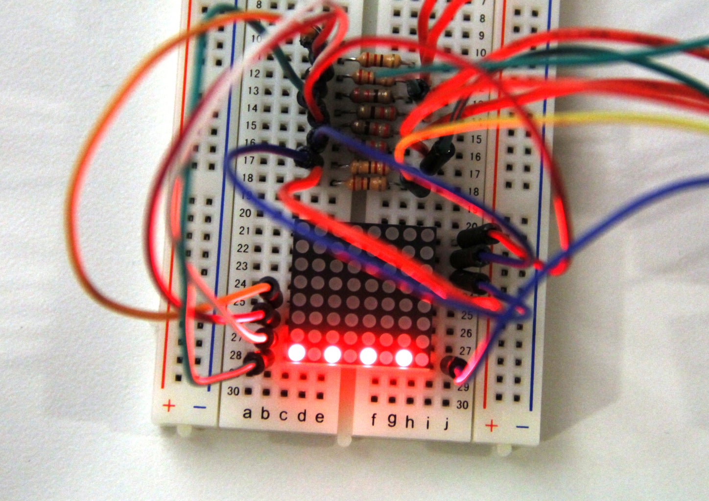
Now unplug all but one of the connections from the row pins to ground, so only one row of LEDs is lit. Instead of connecting the columns to 5V, connect them to the Arduino (still put the current limiting resistors in the circuit). See the third image for a better idea of what this should look like. Here's how the columns should connect to the Arduino:
column 1 - Arduino A0 (analog pin 0)
column 2 - Arduino A1
column 3 - Arduino A2
column 4 - Arduino A3
column 5 - Arduino A4
column 6 - Arduino A5
column 7 - Arduino D2 (digital pin 2)
column 8 - Arduino D3
Run the following code:
void setup(){
  //set pins A0-A6 as outputs
  for (int pinNum=A0;pinNum<A6;pinNum++){
    pinMode(pinNum, OUTPUT);
  }
  //set pins 2 and 3 as outputs
  for (int pinNum=2;pinNum<4;pinNum++){
    pinMode(pinNum, OUTPUT);
  }
}

void loop(){
  //some arbitrary set of states
  digitalWrite(A0, HIGH);
  digitalWrite(A1, LOW);
  digitalWrite(A2, HIGH);
  digitalWrite(A3, LOW);
  digitalWrite(A4, HIGH);
  digitalWrite(A5, LOW);
  digitalWrite(2, HIGH);
  digitalWrite(3, LOW);
}
The only thing a little odd about this code is that we're using analog pins as digital outputs, this is allowed by Arduino. Analog pins can act as digital inputs and outputs, but they have the added functionality of being analog inputs as well. We will be using many of the Arduino's pins in this example (16 total), so I had to start by wiring up some of the analog pins. Another thing, I purposely left pins 0 and 1 with nothing attached to them. The Arduino uses these pins to communicate over USB, and sometimes having things connected to pins 0 and 1 inhibits your ability to program the board.
You should see a pattern of LEDs light up in the row that is connected to ground. One LED on, one off, one on, one off... and so on. This pattern is shown in image #3.
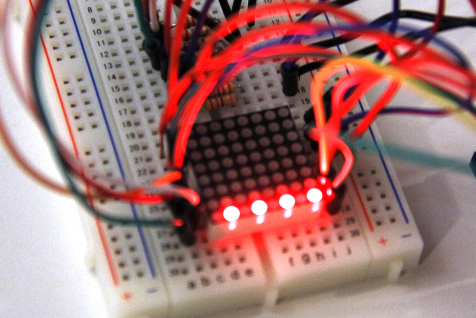
Now remove the connection to ground from the LED matrix, and wire a different row to ground. You should see the same pattern across a different row (image #4). In the next step we'll use the Arduino to selectively ground each row.
First try one more thing, change the pattern of on and off LEDs, here's what I did:
void setup(){
  //set pins A0-A6 as outputs
  for (int pinNum=A0;pinNum<A6;pinNum++){
    pinMode(pinNum, OUTPUT);
  }
  //set pins 2 and 3 as outputs
  for (int pinNum=2;pinNum<4;pinNum++){
    pinMode(pinNum, OUTPUT);
  }
}

void loop(){
  //some arbitrary set of different states
  digitalWrite(A0, LOW);
  digitalWrite(A1, HIGH);
  digitalWrite(A2, LOW);
  digitalWrite(A3, HIGH);
  digitalWrite(A4, LOW);
  digitalWrite(A5, HIGH);
  digitalWrite(2, LOW);
  digitalWrite(3, HIGH);
}
The output is shown in the last image above.
Step 6: LED Matrix Multiplexing


Now wire up all the ground pins of the LED matrix to pins 6-13 of the Arduino. Here are the pin connections:
row 1 - Arduino D6 (digital pin 6)
row 2 - Arduino D7
row 3 - Arduino D8
row 4 - Arduino D9
row 5 - Arduino D10
row 6 - Arduino D11
row 7 - Arduino D12
row 8 - Arduino D13
And run the following code:
void setup(){
  //set pins 6-13 as outputs  and initialize HIGH (so all LEDs are off to start)
  for (int pinNum=6;pinNum<14;pinNum++){
    pinMode(pinNum, OUTPUT);
    digitalWrite(pinNum, HIGH);
  }
  //set pins A0-A6 as outputs
  for (int pinNum=A0;pinNum<A6;pinNum++){
    pinMode(pinNum, OUTPUT);
  }
  //set pins 2 and 3 as outputs
  for (int pinNum=2;pinNum<4;pinNum++){
    pinMode(pinNum, OUTPUT);
  }
}

void loop(){
  for (int pinNum=6;pinNum<14;pinNum++){

    //set columns
    digitalWrite(A0, LOW);
    digitalWrite(A1, HIGH);
    digitalWrite(A2, LOW);
    digitalWrite(A3, HIGH);
    digitalWrite(A4, LOW);
    digitalWrite(A5, HIGH);
    digitalWrite(2, LOW);
    digitalWrite(3, HIGH);

    //pulse row low to light LEDs
    digitalWrite(pinNum, LOW);
    delay(500);
    digitalWrite(pinNum, HIGH);
  }
}
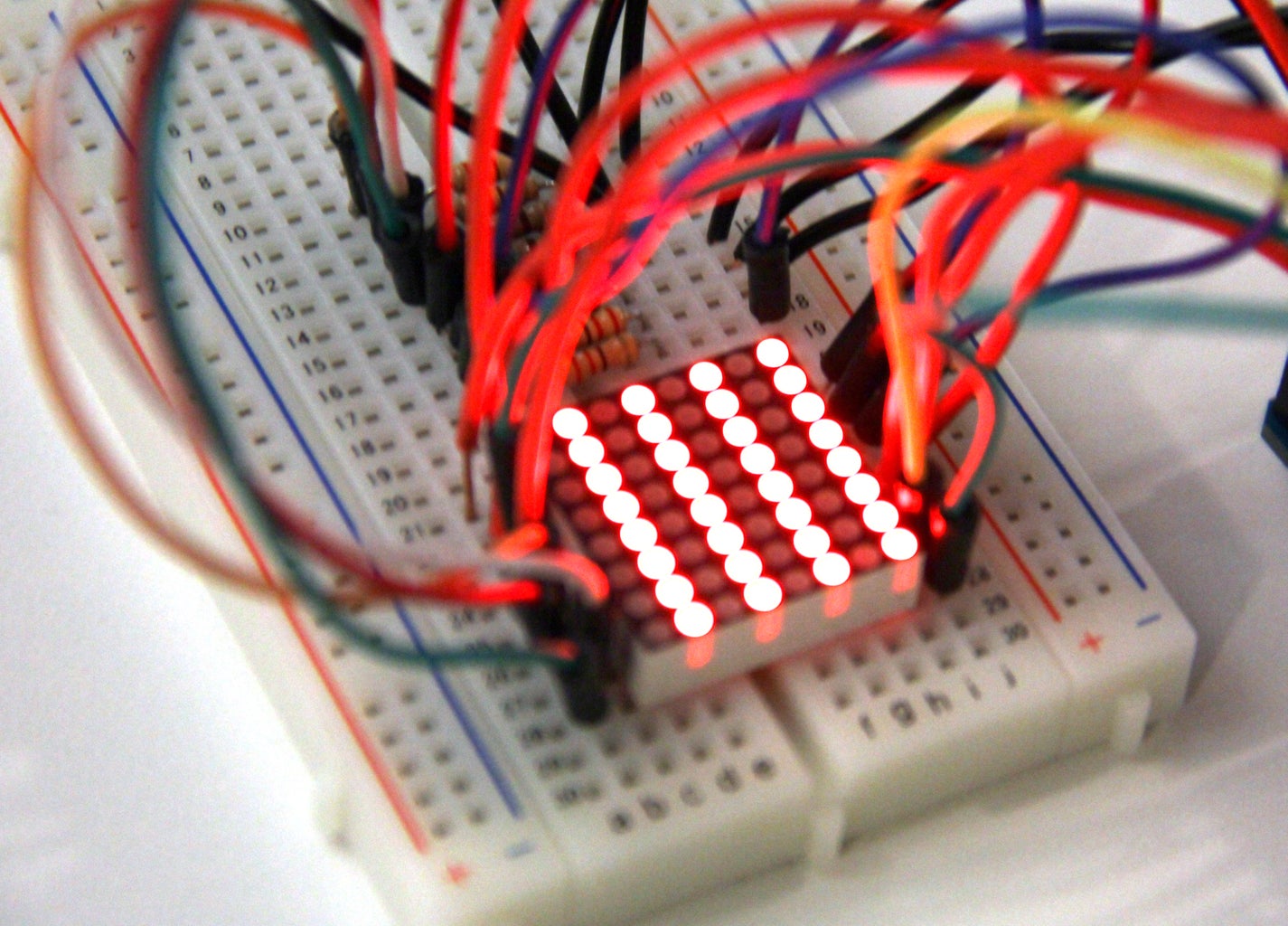
You should see the same pattern of LEDs light up one row at a time (second image) as each row is grounded one by one. Now try decreasing the delay, the pattern will move across the rows faster and faster. Now remove the delay entirely, you should see all the rows lit at (what appears to be) the same time (third image). Here's a video demonstration (this time, using different patterns to light up each row, I'll explain more about that soon):
This is called multiplexing. Even though it looks like we're lighting up many rows of LEDs at the same time, we know that we're actually lighting each row one by one, but we're doing it so fast that we've tricked our eyes into thinking it's all happening simultaneously. Multiplexing is useful any time to want to control a lot of things with relatively few pins. Instead of wiring up each LED individually, we can multiplex them and cut down on costs and hassle significantly.
Now try sending different patterns to different rows:
void setup(){
  //set pins 6-13 as outputs  and initialize HIGH
  for (int pinNum=6;pinNum<14;pinNum++){
    pinMode(pinNum, OUTPUT);
    digitalWrite(pinNum, HIGH);
  }
  //set pins A0-A6 as outputs
  for (int pinNum=A0;pinNum<A6;pinNum++){
    pinMode(pinNum, OUTPUT);
  }
  //set pins 2 and 3 as outputs
  for (int pinNum=2;pinNum<4;pinNum++){
    pinMode(pinNum, OUTPUT);
  }
}

void loop(){
  for (int pinNum=6;pinNum<14;pinNum++){

    if (pinNum%2==1){//is pinNum is odd
      //some arbitrary set of states
      digitalWrite(A0, HIGH);
      digitalWrite(A1, LOW);
      digitalWrite(A2, HIGH);
      digitalWrite(A3, LOW);
      digitalWrite(A4, HIGH);
      digitalWrite(A5, LOW);
      digitalWrite(2, HIGH);
      digitalWrite(3, LOW);
    } else {
      //some arbitrary set of different states
      digitalWrite(A0, LOW);
      digitalWrite(A1, HIGH);
      digitalWrite(A2, LOW);
      digitalWrite(A3, HIGH);
      digitalWrite(A4, LOW);
      digitalWrite(A5, HIGH);
      digitalWrite(2, LOW);
      digitalWrite(3, HIGH);
    }

    digitalWrite(pinNum, LOW);
    delay(500);
    digitalWrite(pinNum, HIGH);
  }
}
Running this code slowly at first, we see that one row is sent one pattern, and the next row is sent a different pattern, this alternates across all the rows in the matrix. Here's how I'm doing this:
if (pinNum%2==1){//is pinNum is odd
% is called "modulo", it is like division, but instead of returning pinNum/2, it returns the remainder of that operation. So if pinNum = 6, pinNum%2 = 0, because 2 goes into 6 evenly. If pinNum = 7, then pinNum%2 = 1. This gives me an easy way of figuring out which rows are even numbers and which are odd. Using this information, I can send different patterns to alternating rows.
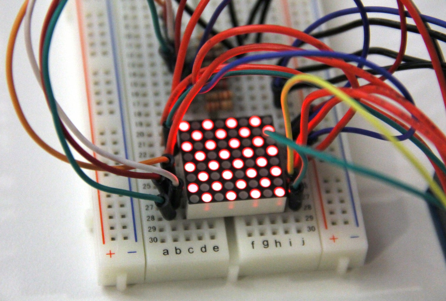
Now try removing the delay from the code. You should see a checkerboard pattern emerge on the LED matrix (fourth image). By sending a different pattern to each row and cycling through the rows individually, you can control exactly which LEDs are on and off. Try the following:
void setup(){
//set pins 6-13 as outputs and initialize HIGH
for (int pinNum=6;pinNum<14;pinNum++){
pinMode(pinNum, OUTPUT);
digitalWrite(pinNum, HIGH);
}
//set pins A0-A6 as outputs
for (int pinNum=A0;pinNum<A6;pinNum++){
pinMode(pinNum, OUTPUT);
}
//set pins 2 and 3 as outputs
for (int pinNum=2;pinNum<4;pinNum++){
pinMode(pinNum, OUTPUT);
}
}
void loop(){
for (int pinNum=6;pinNum<14;pinNum++){
if (pinNum==8){
digitalWrite(A5, HIGH);
} else {
digitalWrite(A5, LOW);
}
digitalWrite(pinNum, LOW);
digitalWrite(pinNum, HIGH);
}
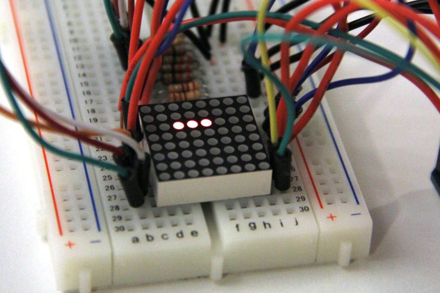
}This code will only set A5 HIGH for the row connected to pin 8. This lights up only one LED in the matrix (fifth image).
Step 7: Sending Bytes to a Multiplexed LED Matrix
So far the code we've been using to send data out to the LED is a bit awkward to write. It has involved explicitly assigning a HIGH or LOW state to each of the Arduino pins connected to a column. If we wanted to program the matrix to display a different pattern for each of its 8 rows, we will have to write a lot of line of code. Here's a way to organize things:
void setup(){
  //set pins 6-13 as outputs  and initialize HIGH
  for (int pinNum=6;pinNum<14;pinNum++){
    pinMode(pinNum, OUTPUT);
    digitalWrite(pinNum, HIGH);
  }
  //set pins A0-A6 as outputs
  for (int pinNum=A0;pinNum<A6;pinNum++){
    pinMode(pinNum, OUTPUT);
  }
  //set pins 2 and 3 as outputs
  for (int pinNum=2;pinNum<4;pinNum++){
    pinMode(pinNum, OUTPUT);
  }
}

void loop(){
  for (int pinNum=6;pinNum<14;pinNum++){

    if (pinNum==8){
      setStates(56);
    } else {
      setStates(0);
    }

    digitalWrite(pinNum, LOW);
    digitalWrite(pinNum, HIGH);
  }
}

void setStates(byte states){
  zeroStates();//first turn all pins off
  //look at each bit of binary number and set HIGH if needed
  if (states & 1) digitalWrite(A0, HIGH);//check the first bit (least significant bit)
  if (states & 2) digitalWrite(A1, HIGH);//check the second bit
  if (states & 4) digitalWrite(A2, HIGH);
  if (states & 8) digitalWrite(A3, HIGH);
  if (states & 16) digitalWrite(A4, HIGH);
  if (states & 32) digitalWrite(A5, HIGH);
  if (states & 64) digitalWrite(2, HIGH);
  if (states & 128) digitalWrite(3, HIGH);//check the most significant bit
}

void zeroStates(){
  digitalWrite(A0, LOW);
  digitalWrite(A1, LOW);
  digitalWrite(A2, LOW);
  digitalWrite(A3, LOW);
  digitalWrite(A4, LOW);
  digitalWrite(A5, LOW);
  digitalWrite(2, LOW);
  digitalWrite(3, LOW);
}
Remember how we used a number between 0 and 255 (a byte) to set the states of 8 LEDs connected to the 595? Now I've added a function called setStates() that lets us set the states of 8 LEDs in each row of the LED matrix using a byte. The first thing setStates does is set all the pins connected to LED matrix columns LOW to turn off any LEDs that might be on. Then it checks each binary digit of the 8-digit byte using the & operator; if any of the digits are 1, it sets the corresponding pin HIGH.
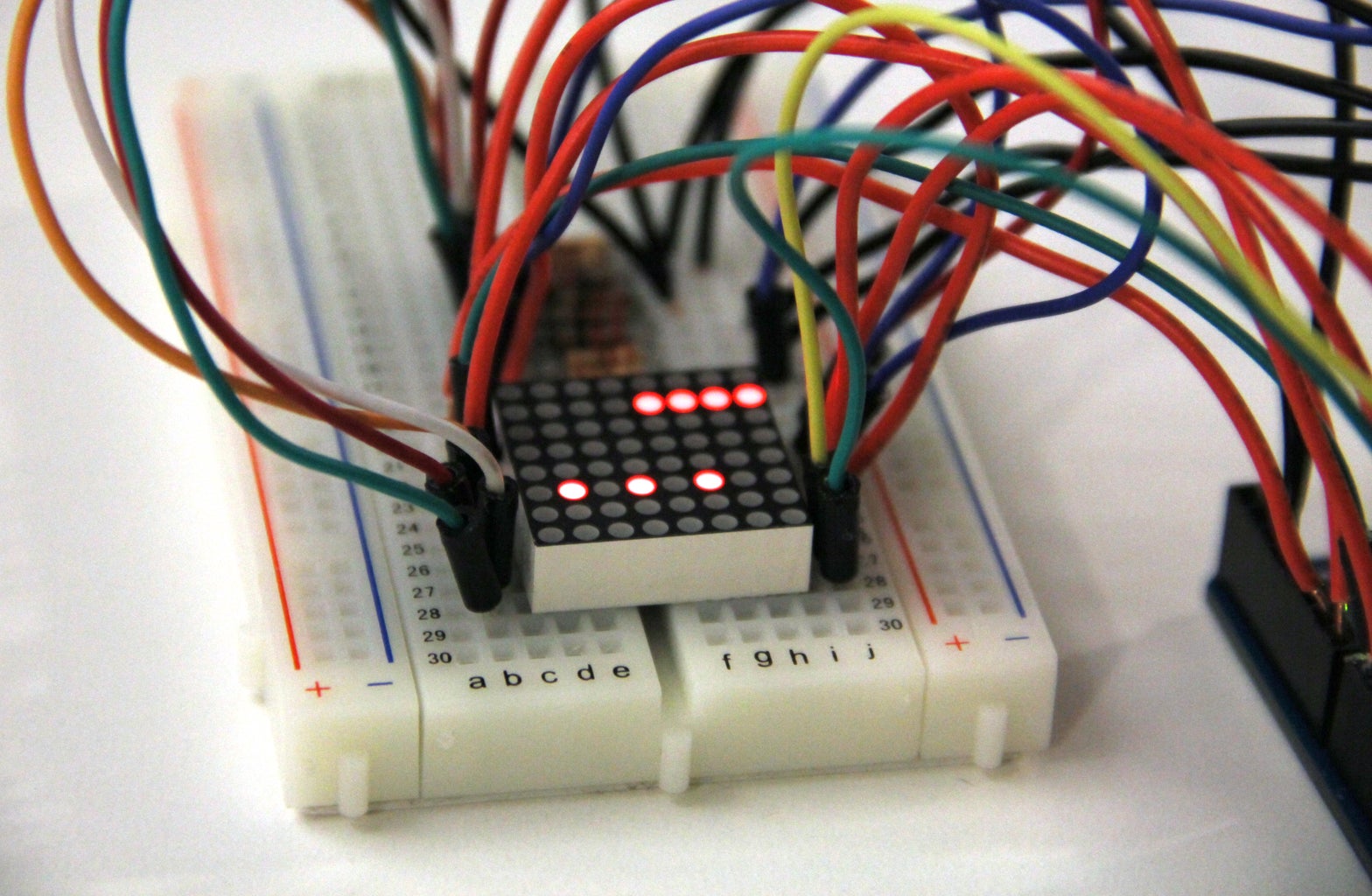
The code above sets the row connected to digital pin 8 using the number 56. In binary, 56 is represented as:
00111000
And the resulting LED output is shown in the first image above, you can see that each 1 in the binary number corresponds to a lit LED in the matrix.
Next try programming each row in the LED matrix to display the number of the digital pin it is attached to:
void setup(){
  //set pins 6-13 as outputs  and initialize HIGH
  for (int pinNum=6;pinNum<14;pinNum++){
    pinMode(pinNum, OUTPUT);
    digitalWrite(pinNum, HIGH);
  }
  //set pins A0-A6 as outputs
  for (int pinNum=A0;pinNum<A6;pinNum++){
    pinMode(pinNum, OUTPUT);
  }
  //set pins 2 and 3 as outputs
  for (int pinNum=2;pinNum<4;pinNum++){
    pinMode(pinNum, OUTPUT);
  }
}

void loop(){
  for (int pinNum=6;pinNum<14;pinNum++){

    setStates(pinNum);

    digitalWrite(pinNum, LOW);
    digitalWrite(pinNum, HIGH);
  }
}

void setStates(byte states){
  zeroStates();//first turn all pins off
  //look at each bit of binary number and set HIGH if need
  if (states & 1) digitalWrite(A0, HIGH);
  if (states & 2) digitalWrite(A1, HIGH);
  if (states & 4) digitalWrite(A2, HIGH);
  if (states & 8) digitalWrite(A3, HIGH);
  if (states & 16) digitalWrite(A4, HIGH);
  if (states & 32) digitalWrite(A5, HIGH);
  if (states & 64) digitalWrite(2, HIGH);
  if (states & 128) digitalWrite(3, HIGH);
}

void zeroStates(){
  digitalWrite(A0, LOW);
  digitalWrite(A1, LOW);
  digitalWrite(A2, LOW);
  digitalWrite(A3, LOW);
  digitalWrite(A4, LOW);
  digitalWrite(A5, LOW);
  digitalWrite(2, LOW);
  digitalWrite(3, LOW);
}
The output is shown in the second image above.
Step 8: Using an Array to Store and Set the States of an LED Matrix
In the last step we saw how using bytes simplified the process of setting the states of each row in the LED matrix. Now we'll take a look at a strategy for storing that information in an array. An array is a place where we can store a collection of related variables, in this case, I'll be using an array to store the states of each row int he matrix. Since we're representing the states of each row int he matrix using a byte, and there are 8 rows, I will need an array of 8 bytes to store the states of all 64 LEDs in the LED matrix. Here's how the array is created
byte ledStates[8] = {0, 15, 0, 0, 0, 84, 0, 0};
I've initialized the array with a set of bytes, I threw in some non-zero bytes to see how they show up on the LED matrix. Here's how the array is used:
byte ledStates[8] = {0, 15, 0, 0, 0, 84, 0, 0};


void setup(){
  //set pins 6-13 as outputs  and initialize HIGH
  for (int pinNum=6;pinNum<14;pinNum++){
    pinMode(pinNum, OUTPUT);
    digitalWrite(pinNum, HIGH);
  }
  //set pins A0-A6 as outputs
  for (int pinNum=A0;pinNum<A6;pinNum++){
    pinMode(pinNum, OUTPUT);
  }
  //set pins 2 and 3 as outputs
  for (int pinNum=2;pinNum<4;pinNum++){
    pinMode(pinNum, OUTPUT);
  }
}

void loop(){
  for (int i=0;i<8;i++){

    setStates(ledStates[i]);

    int pinNum = getPinNumForLEDIndex(i);
    digitalWrite(pinNum, LOW);
    digitalWrite(pinNum, HIGH);
  }
}

int getPinNumForLEDIndex(int index){
  return index+6;
}

void setStates(byte states){
  zeroStates();//first turn all pins off
  //look at each bit of binary number and set HIGH if need
  if (states & 1) digitalWrite(A0, HIGH);
  if (states & 2) digitalWrite(A1, HIGH);
  if (states & 4) digitalWrite(A2, HIGH);
  if (states & 8) digitalWrite(A3, HIGH);
  if (states & 16) digitalWrite(A4, HIGH);
  if (states & 32) digitalWrite(A5, HIGH);
  if (states & 64) digitalWrite(2, HIGH);
  if (states & 128) digitalWrite(3, HIGH);
}

void zeroStates(){
  digitalWrite(A0, LOW);
  digitalWrite(A1, LOW);
  digitalWrite(A2, LOW);
  digitalWrite(A3, LOW);
  digitalWrite(A4, LOW);
  digitalWrite(A5, LOW);
  digitalWrite(2, LOW);
  digitalWrite(3, LOW);
}
In order to get a variable stored in an array, you use the following syntax:
arrayName[variableIndex]
where variableIndex is the location of the variable in the array. For example:
ledStates[0] equals 0
ledStates[1] equals 15
because the first (index = 0) element in the array is 0, and the second (index = 1) element in the array is 15.
Since I'm no longer iterating over the pinNums in my for loop, I created a helper function that converts between my iterator variable "i" and the Arduino pin connected to the row of interest:
int getPinNumForLEDIndex(int index){
return index+6;
}
Try changing the bytes in the array ledStates to see how they affect the output of the matrix. Also try changing the variables stored in ledStates as the sketch runs, use the following syntax:
ledStates[indexNum] = newValue
You can also set the states of the LEDs using bytes that are written the following way:
B11011011
The B lets Arduino know that it should expect a binary number, then the next 8 numbers are the 8 digits in binary you want to display. This makes it a little easier to design a 2D pattern on the LED matrix. Try using this array:
byte ledStates[8] = {B0111100, B01000010, B10110101, B10000101, B10000101, B10110101, B01000010, B0111100};
Step 9: Controlling an LED Matrix With a Chip
This circuit is using up a ton of Arduino pins so far. In case you need to connect other things to your Arduino, try using the 595 code and the LED matrix code to control the matrix using fewer Arduino pins (hint-connect the 595's 8 outputs to the 8 columns of the 8 rows of the LED matrix). You can even use two 595's, one to control the rows and another to control the columns. One thing to be aware of is that neither the Arduino pins or 595 are able to provide enough current to drive an entire row of LEDs at full brightness, so you might want to use something like the TPIC6B595 (a high-power shift register) if you're concerned about brightness.
This same idea (multiplexing) can be used to control a grid of inputs, like buttons. I won't get into the details in this post, but you can find more info about that here (one slight difference between multiplexing buttons vs multiplexing LEDs is that when you wire buttons in a grid, you will also need to connect a diode to each button - the 1N4148 is good). If you're interested in working with grids of buttons and LEDs, you might want to check out this backlit button pad and PCB from Sparkfun.
The easiest way I've found to control an LEd matrix is with the MAX7219 chip, it basically handles all the multiplexing internally, each chip can control up to 64 LEDs, and it requires only 3 of the Arduino's digital output pins, though it is a little pricey at around $11 each. There is a ton of info about using that chip on the Arduino website. The MAX7219 will not let you adjust the brightness of the LEDs individually, it will only control their on/off state. If you need to control the brightness of many LEDs, you might check out the TLC5940 (Arduino library here), though I admit, it is tricky to multiplex with this chip because of certain timing considerations - that would be a somewhat advanced project - but each chip easily controls 16 LEDs and you can daisychain them together to control more.

Participated in the
123D Circuits Contest


