

Introduction: Easy Aircraft Design

Hey Guys,
My friends at Dual Design R/C and I wanted to give you all open ended step-by-step instructions on how to design a basic airplane with a large degree of artistic freedom and easy mathematics! You will need to watch the units you use! No crazy engineering needed here. I'll be using an example of a conventional airplane with the main wing in front of the stabilizers (Stab). I'll also be using simple tapered wings to keep complexity low.
Step 1: Sketch
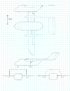
To start out analyzing your design you'll need a 3 view drawing of your plane on a piece of paper. I suggest a scale drawing on a piece of graph paper. Keep it simple, and keep it boxy. Boxy is easier to build! Here is a great example below.
Step 2: Measure

In aircraft design there are some critical measures that will determine if your plane will fly. Those measures are the Static Margin (SM), Center of Gravity (CG), Horizontal Stabilizer Volume (VH), Vertical Stabilizer Volume (VV), and Cubic Wing Loading (CWL).
When power is concerned the additional measures of Power-to-Weight Ratio (P/W) and Thrust-to-Weight Ratio (T/W) are very important.
In order to find these key measures we must first find a few other measures before hand. These measures would be the dimensions and areas of the main wing, horizontal and vertical stabilizers, the aerodynamic centers (AC), Neutral Point (NP), and the distance between the two centers. Don't worry about the AC and NP yet, I'll show you how to find them!
When finding the area and dimensions, the critical ones are the labeled dimensions A (Root Chord), B (Semi-Span), & C (Tip Chord) in the picture below;
Step 3: Find the Aerodynamic Center (AC)

With those dimensions and areas recorded we now move onto finding the Aerodynamic Center.
The AC is where all the aerodynamic forces act of the wing. It is like a CG but for air.
Below is a graphical representation of how to find AC of a wing panel by using the Mean Aerodynamic Chord (MAC) or Geometric Mean Chord (GMC). This method will work for most wings, tapered or not. Take the lengths you found before and add the tip chord measure (C) in front of and behind the Root Chord (A). Next add the Root Chord (A) in front of and behind the Tip Chord (C). Draw a diagonal line from each end of the newly created lines and find where the two intersect. Now measure the distance of the GMC as seen in the picture below. Write this length down as it is important!
With the GMC found, take 25% (1/4) of that distance from the leading edge and trace over to the root of the wing panel. This point is the Aerodynamic Center of the wing panel. Find this point for the main wing and stabilizers before continuing.
Step 4: Find the Neutral Point (NP)

Next Stop, Neutral Point! (NP)
With the AC of all your wing panels found, we can find the NP of your airplane. The NP is like the AC of your entire airplane.
With your drawing ready, measure L (The distance between the AC of the Main Wing and Horizontal Stab.) and use that in addition to the areas of both to find the length D. The equation is listed in the middle of the three in the picture below. We can now use D to find the location of NP by subtracting it from L.
Step 5: Find the Center of Gravity (CG) With the Static Margin (SM)

Great! Now we can find the location of the Center of Gravity (CG).
This is found by determining the Static Margin. The Static Margin is a measure of stability of your plane. Typically the SM is a distance based on the length of the GMC or MAC. Most planes have a SM of 5% to 15% of the MAC which means the CG is 5% MAC to 15% MAC in front of the NP. A plane with a Static Margin of 5% is limited in stability and 15% is great stability. Never put the CG behind the NP!!!!! Just don't do it! You've been warned.
Step 6: Calculate the Horizontal Tail Volumes (HV)

Awesome!
We have NP, ACs, and CG found. What is next? the Tail Volumes! What are they? They are a measure of the effectiveness of the stabilizers. We'll start with the horizontal stabilizer. Using the Areas, Lengths, and MAC use the equation at the top of the first picture below to find the Horizontal Stabilizer Volume (VH). Typical values for this are between .35 and .8. .35 is less effective and .8 is SUPER effective.
Step 7: Calculate the Vertical Tail Volumes (VV)

Now we can move onto finding the Vertical Stabilizer Volume (VV). Below is a photo of how to find VV.
Using the areas and distances once again, use the equation listed above and find VV. Typical values for VV are between .02 and .05. Once again .02 is a less effective tail and .05 is a SUPER effective tail.
Step 8: Calculate the Cubic Wing Loading (CWL)

Wow, so we actually are almost done. Congrats on making it this far! Last but not least is a little secret called the Cubic Wing Loading (CWL). CWL is the responsible big brother of regular 2D wing loading. What do I mean? This value doesn't change with scale which means a full scale plane and model version of the same plane should have the same CWL if they want have the same flight characteristics. To find this, it gets a bit tricky. Use the equation below to help. WCL equals the weight of your plane divided by the wing area multiplied by the square root of the wing area.
Similar aircraft have a range of WCL which dictates their flight abilities. Here is a short list of those values;
0-4 oz/ft^3 = Gliders
4-7 oz/ft^3 = Trainers
7-13 oz/ft^3 = Sport/Aerobatic
13+ oz/ft^3 = Racing
Depending on what type of plane you are designing, pick a value to use it to find the weight of your plane in oz. This will give you a goal for what your plane should weigh before you take off! By this I mean the All Up Weight (AUW) with batteries or fuel installed. It is a great point to work backwards from the find the suggested weight of your airframe once you have your electronics selected.
Step 9: Determine Power Requirements
Speaking of electronics, one last tidbit of information to help make sure your aircraft will fly. Power is an important factor for model aircraft. Here are two great ratios to consider in the design of your airplane. These are the mentioned ratio of Power-to-Weight (P/W) and Thrust-to-Weight (T/W). There is a general range of P/W that dictates performance. It is listed below;
25 W/lb = Minimum for level flight
50 W/lb = Trainer or Casual flight
75 W/lb = Sport/Aerobatic flight
100 W/lb = Aggressive Aerobatic flight
150 W/lb = 3D Aerobatic flight
200 W/lb = Unlimited high-speed vertical flight
Use the specifications of your motor to find the Wattage (Power) of your system and use that to determine the P/W.
For example a certain motor I use has a rated power of 150W when running on 3S Lipos. I take that 150W and divide that by the airplane's AUW.
Now we come to the final measure. Whew, so much work but only a little left until you get to go building! Or redesigning if your design fell short. But once you get all other measures confirmed, to help choose a prop or power system, the Static Trust-to-Weight ratio is suggested to be around .50. This will help ensure you have enough power to power around the sky and not fall like a brick. Use data from the motor manufacturer, flying buddies, or electronic calculators to help figure this out. Other than that that's all there is the aircraft design for the weekend warrior.
That's all folks!
Step 10: Conclusion
I hope you gain some great info from this article. It summarizes my understanding of aircraft design and hopefully aids other as well.
Now, the next step is for you to build your creation! I would suggest a boxy foam and tape method much like timcarlielle and tak145 did here in instructables.
Feel free to comment, PM, or email me with further questions or requests.
Also, thanks to my friends over at Dual Design R/C for confirming my thoughts and aiding me in writing this article.
FlyBoy38L


