

Introduction: IoT Enabled Coffee Machine


This instructable is entered in to the IoT competition - If you like it, please vote for it!
UPDATED: Now supports 2 way comms and OTA updates
For some time now I have had a Jura coffee machine and I have always wanted to automate it somehow.
I have been running a basic home automation system for some years but the coffee machine was not something that was simple to mod (or so I thought). Jura coffee machines generally have a 'Diagnostic port' and/or a port used for adding a payment system to the machine, however I could not find any information on how it could be utilised. More recently, the protocol was reverse-engineered by some individuals and made public. The problem was, most of the references to the functions available were for much larger machines than mine (Ena 7).
On top of that, my machine does not have a permanent standby power like the bigger machines, instead it has a HV switch that makes the power supply 'latch on'. The physical button on the machine actually activates 2 switches - One low volt (logic side, turn off) and one High Volt (Power on). Both switches are momentary.
I also needed to make sure that the machine still operated 100% independent of any control mechanism, i.e the machine still functions as normal as if it was not IoT enabled.
To automate the machine requires two things:
1) To be able to control the power to the machine
2) To be able to communicate with the machine to activate the functions for making coffee, rinse etc.
Step 1: How We Are Going to Do It
We will use an ESP8266 'ESP-01' module to connect to the home wifi and subscribe to MQTT server/topic listening for commands. The 'Front End' I used is OpenHAB2 but there is no reason you could not add to the web interface on the device and control directly if you wanted to or via HTTP Get commands.
The ESP8266 will handle controlling 2 relays related to the power button and also process serial commands to/from the coffee machine.
WARNING - This instructable outlines the procedure I used to modify my Jura Ena7 coffee machine to be controlled via home automation. It deals with modifying a mains electricity device which can be dangerous if performed incorrectly. Information here may be incomplete, inaccurate and unsafe. Proceed with caution. No liability accepted.
Step 2: Equipement Needed


Parts
- ESP-01 module and a way to program it (Arduino IDE and physical adaptor for programming)
- 2 way relay module EBAY
- 5v -> 3.3v Regulator EBAY
- Small 5v mains powered phone charger
- Logic level converter* Freetronics
- Misc wire, pin headers, heat shrink etc for connecting it all up.
Tools
- Fine tipped soldering Iron
- Solder
- Wire Strippers are handy
- Torx T15 Driver
- Oval security tool (or make one, only takes a few mins)
*I initially used an arduino UNO in my testing of all the serial commands to the machine and it worked flawlessly, however the ESP module refused to work. I triple checked the code and I was certain that the commands exiting the ESP module were the same as the arduino however it was a no-go. I put this down to the ESP module only working on 3.3v logic and not 5V. Once I put in the Logic converter, it worked fine. This may or may not be required in other machines.
Ideally, you would have an existing home automation system that supports the MQTT protocol (such as openhab) as this is what the project is aimed at. If you just want to control it via buttons on a web page without any supporting systems, you will need to make some changes to the embedded web page code. It is not overly complicated to achieve (maybe rev2..)
Step 3: The Jura Protocol

The data to/from the machine is just serial @ 9600 but Jura have some tricks up their sleeves too. The protocol either uses this for extra ECC and/or to obfusicate the communication. Simply put, each byte of data (character) is split across bits 2 and 5 of 4 standard serial bytes trailed by an 8ms pause. If you care to learn how this works, there is plenty of information in the links here.
Protocol Information extracted from: http://protocoljura.wiki-site.com/
The arduino code simplifies this, enabling you to transmit standard, human readable commands which it then transposes into the Jura protocol.
My code is a combination of code from:
https://github.com/oliverk71/Coffeemaker-Payment-...
https://github.com/psct/sharespresso
The commands referenced at the sites above were not accurate for my machine but through a method of trial and error, I was able to come up with the below:
FA:01 - Turns off (but does not seem to rinse, even if needed)
FA:02 - Responds 'ok' but not sure what it does.
FA:03 - Rinse Message (Forces a 'rinse' message on the screen, pressing rotary rinses machine)
FA:04 - Rinse Action - Rinses when 'Press Rotary button' message appears, otherwise does nothing
FA:05 - Strong on screen (Presumably combine this with making a coffee for strong)
FA:06 - Strong on screen (Presumably combine this with making a coffee for strong)
FA:07 - 'Special' on screen but does not actually do anything, not sure what this is for
FA:08 - Steam
FA:09 - Small Coffee
FA:0A - Large Coffee
There are other commands but this is plenty for me...
Exercise caution when issuing unknown commands, for example, apparently AN:0A will wipe the EEPROM of the machine...
Step 4: Disassembly
Getting the machine itself open is not overly easy as you need some slightly special tools but a keen person will find a way - You need a T15 Torx bit and an 'oval key' for 2 screws. The Torx I already had, the oval tool I made out of a 4mm socket head bolt drilled out and flattened a bit with a hammer.
The instructions here are fairly well presented - http://marius.me.uk/blog/2015/03/open-jura-ena-5/
Step 5: Voiding the Warranty


Once into the machine, you will see the main components. The main power inlet has a nice spot under it for adding the 5v charger.
I added (mains rated) wires to the terminal block at the entry of the machine and soldered/heatshrinked these to the mains pins of the 5v charger. My particular model was not a USB port type but one that had the lead permanently attached. You may not have enough room for a usb port type one to be able to use an actual USB cable but if you opened up the charger, you could remove the USB port and replace with a standard wire to the 5v and Gnd points.
You could substitute another mains rated 5v power supply if you like. 500ma should be plenty.
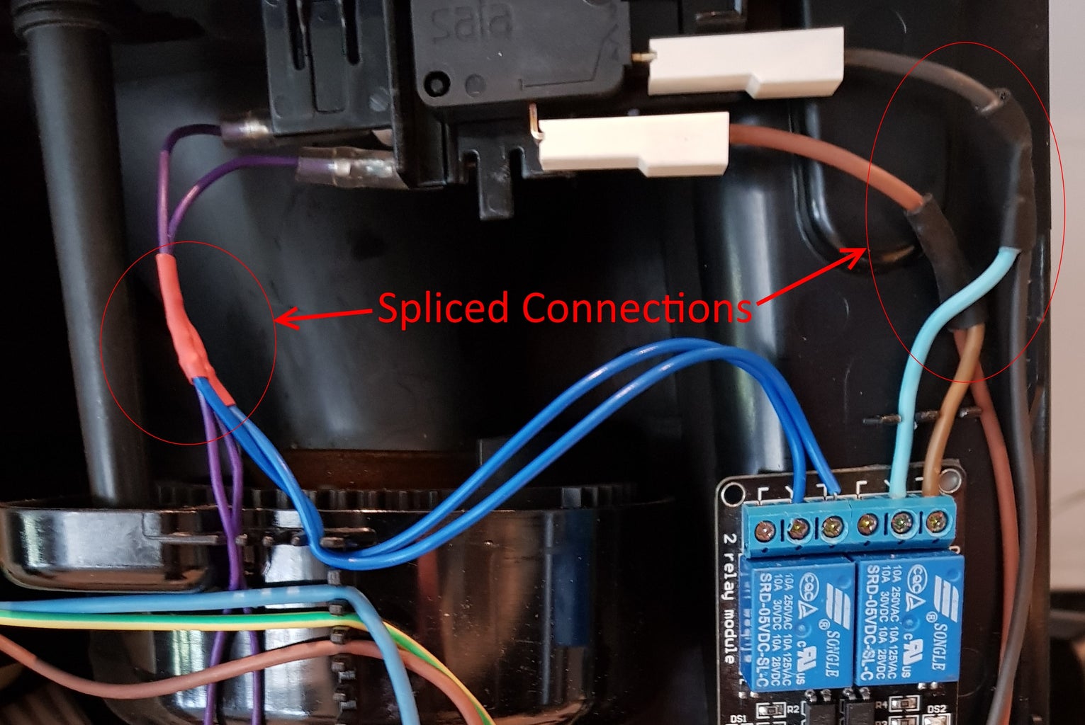
There is plenty of room for the relay module up near the grinder. We have to wire the two relays to operate in parallel with the main power switches. I simply cut the existing wires, stripped, tinned, added an extra wire in and soldered back together (don't forget heatshrink). There was enough slack in the wires to do this.
The relay module is held in place with good quality double sided tape. With the wires connected and with only limited space for movement, even if the tape does lose grip, the module will not go too far and can not come in contact with any metal objects.
I also backprobed the diagnostic port on my machine to determine the location of the internal connections so I could achieve a completely hidden integration. Only tx, rx and Gnd wires are used.
If you have a more commercial machine that supports a standby voltage and/or you do not want to void warranty on your machine, you can connect directly to the diagnostic port instead but may not be able to power on the machine using this device.
My machine uses a 7 pin connector. From left to right it is:
NC Tx G Rx NC 5v NC
The corresponding pins on the mainboard: Red = Gnd Orange = Rx Black = Tx
More info can be found on the pinouts here: http://protocoljura.wiki-site.com/index.php/Serial_interfaces
Step 6: Wiring the Logic Side


Review the diagram - It looks overly complicated but it really isn't.
I mounted the level converter to the back of the (depinned) voltage regulator with some double sided tape. I then used some component legs to solder the power and ground pins on either side of the level converter to the corresponding power module pins. This whole module then works like a 'passthrough' for all of the logic and power supply for the ESP-01.
I used the two middle converters for the serial data and the outer two for the relay driving signals but it does not matter which you use.
It's not actually necessary with these relay modules to run a 5v logic as they are active LOW but it just worked nicely so i did it anyway.
I used a 4x2 female header for connecting to the ESP module. This allows for easy uploading of code or replacing the module.
Not pictured in the diagram is the 5V input - I wired mine directly to the relay module (see second picture). The black wire to the bottom left of the picture is the serial data off to the main board. I used a part of a shielded 3.5mm headphone extension cable just to help reduce the chances of interference in the data line.
The 12f code uses SoftwareSerial instead of hardware serial - This allows the module to report status for debugging back via normal serial. Connections are via pins 4 and 5 instead. I adapted the same header to make the ESP12F a plug in swap for the ESP-01, just swapping those serial pins.
Step 7: Programming the Module

Code was compiled against Arduino 1.8.1 with ESP8266 board addon and PubSubClient 2.6.0 (which is the MQTT Library)
Modify the code as per your requirements and upload the code to the ESP-01 module and connect to the machine. Be careful with the orientation of the pins!
Configuration
Option 1)
Only on base code in zip.
When the ESP module first boots, it goes in to AP mode and sets it's IP to 192.168.4.1. You can then connect to the module and change the IP and connect to your own access point. You will also need to set an IP for your machine in that range as there is no DHCP on the module.
Default AP SSID is 'ESPSwitch' and the password is '12345678'
It stays in AP mode for 2 minutes by default. You can change this setting in 'global.h' - It is called 'adminTimeout' and is in milliseconds. I recommend changing this to something low once you have a valid config in EEPROM as it will just cause unnecessary delays in the boot of the device otherwise.
Option 2)
This is the default mode for the newer code that supports 2 way comms, option 1 is not available.
You can also change the default SSID/Password settings in the main ino file (look for '// DEFAULT CONFIG') so it will load those settings into the EEPROM on first boot and change admin mode delay to something low in 'global.h'. This avoids having to mess around connecting to the temporary AP.
The device will automatically set it's MQTT id (and subscription path) to the last 4 digits of the modules serial number. The path by default is ha/mod/<4 digit ID>/#, change as you see fit but read the comments in the code to make sure the appropriate array has the correct length.
I do this because it means I don't have to generate a unique ID for every module on my network.
The device ID is visible and the MQTT server can be set via the MQTT server page on the internal web server.

Step 8: Making It Do Stuff...
The MQTT commands are
ha/mod/xxxx/ 0 or 1 = Toggle power

Any other string will be treated as a command and sent via serial port.

Status is reported to /ha/coffee in HEX
With OpenHAB
coffeemachine.items
Number  Coffee_Machine_Power  "Power"  <power>  { mqtt=">[control:ha/mod/8002/:command:*:default]" }
String  Coffee_Machine_Status                   { mqtt="<[control:ha/coffee:state:default]" }
Sitemap
Group item="Coffee Machine" {
       Switch item=Coffee_Machine_Power label="Power" mappings=[1="Toggle"]
       Switch item=Coffee_Machine_Cmd label="" mappings=["FA:09"="Small"]
       Switch item=Coffee_Machine_Cmd label="" mappings=["FA:0A"="Large"]
       Switch item=Coffee_Machine_Cmd label="" mappings=["FA:04"="Rinse"]
       Text   item=Coffee_Status label="Status [%s]"
     }
voicecontrol.rules
import org.openhab.model.script.actions.*<br>import org.openhab.core.library.types.*
import java.util.*</p><p>rule "Voice command Rules"
when
  Item VoiceCommand received command
then
  var String command = VoiceCommand.state.toString.toLowerCase
  logInfo("Voice.Rec","VoiceCommand received "+command)</p><p>  if (command.contains("turn on the coffee machine") || command.contains("turn off the coffee machine")) {
    sendCommand(Coffee_Machine_Power, 1)
  }
  if (command.contains("make me a small coffee")) {
    sendCommand(Coffee_Machine_Cmd, "FA:09")
  }
  if (command.contains("make me a large coffee")) {
    sendCommand(Coffee_Machine_Cmd, "FA:0A")
  }
  if (command.contains("rinse the coffee machine")) {
    sendCommand(Coffee_Machine_Cmd, "FA:04")
  }
}
end
Rules (for interpreting HEX responses into 'real' values):
rule "Coffee Machine Status"
when Item Coffee_Machine_Status received update then var String response = Coffee_Machine_Status.state.toString() if (response.indexOf("ic:") > -1) { var String hexString = response.substring(3,5)var int num = (Integer.parseInt(hexString, 16)); var String binaryString = String.format("%8s", Integer.toBinaryString(num)).replace(' ', '0')
var int trayBit = binaryString.substring(0,1) var int tankBit = binaryString.substring(2,3) var int heatBit = binaryString.substring(7,8) var int rinseBit = binaryString.substring(6,7)
if (trayBit == "0") { postUpdate(Coffee_Status, "Tray Missing") } if (tankBit == "1") { postUpdate(Coffee_Status, "Fill Tank") } if (rinseBit == "1") { postUpdate(Coffee_Status, "Press Rotary") } if (trayBit == "1" && tankBit == "0" && rinseBit == "0") { postUpdate(Coffee_Status, "Ready") }
} if (response == "Off"){ postUpdate(Coffee_Status, "Off") } end
Step 9: Refinements/Todo
Simplify initial setup connecting to wifi - Done. Abandoned the idea of 'admin mode' as it was annoying. Now just enter SSID and password in code. Saves to EEPROM if you update/change via web interface.
Newer code also supports OTA updates but you will need to upgrade the EEPROM on the ESP-01 module for this to work or comment out the corresponding OTA items.
Add code for processing responses from the machine and read status like no tray, empty grounds and fill tank - Done. I have added code to read the status back and publish to ha/coffee. This is just the raw responses and I am still working on interpreting them but so far I have Tray missing and Tank empty working. It polls the machine every 9 seconds when on and publishes the response to MQTT.
The response is in HEX but individual bits indicate the sensors.
Add code to the webpages for direct control via HTTP GET Commands.

First Prize in the
Internet of Things Contest 2017


