

Introduction: IoT Made Simple: Home Weather Station With NodeMCU and OLED


This Instructable was selected as a winner on both, "Sensors"and "Micro Controller" contests. Thanks a lot for all your votes! ;-)
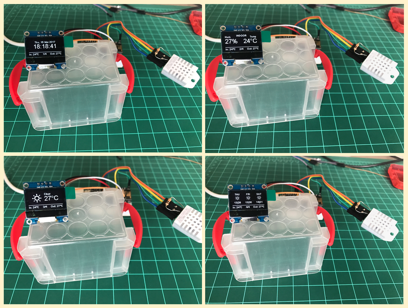
Let's continuous our IoT exploration, with the NodeMCU. On this tutorial, we will develop a Home Weather Station, where we will display outdoor information as temperature and climate conditions including the present day and a 3 days forecast. Our station will also display indoor information as temperature and air humidity.
The above Block diagram gives us a general overview of the project.
At bellow video you can see the final project working:
Step 1: Bill of Material (BoM)

(All values are referencial in USD)
- NodeMCU ESP8266-12E ($8.79)
- 0.96" I2C IIC SPI Serial 128X64 White OLED LCD LED Display Module ($8.99)
- DHT22 AM2302 Temperature And Humidity Sensor ($9.88)
- Mini BreadBoard ($1.00)
- Male-Female Dupont Cables ($1.00)
- External 5V power Supply or battery
Step 2: Installing the OLED on NODEMCU


I assumed that you have your Arduino IDE already prepared with the required libraries to run the NodeMCU code. If not, please visit my awarded tutorial: From Blink to Blynk, an IoT Journey on the Wings of NodeMCU ESP-12E
Now it's time to install the OLED display, our old friend, SSD1306, wich main characteristics are:
- Display size: 0.96"
- I2C IIC SPI Serial
- 128X64
- White OLED LCD LED
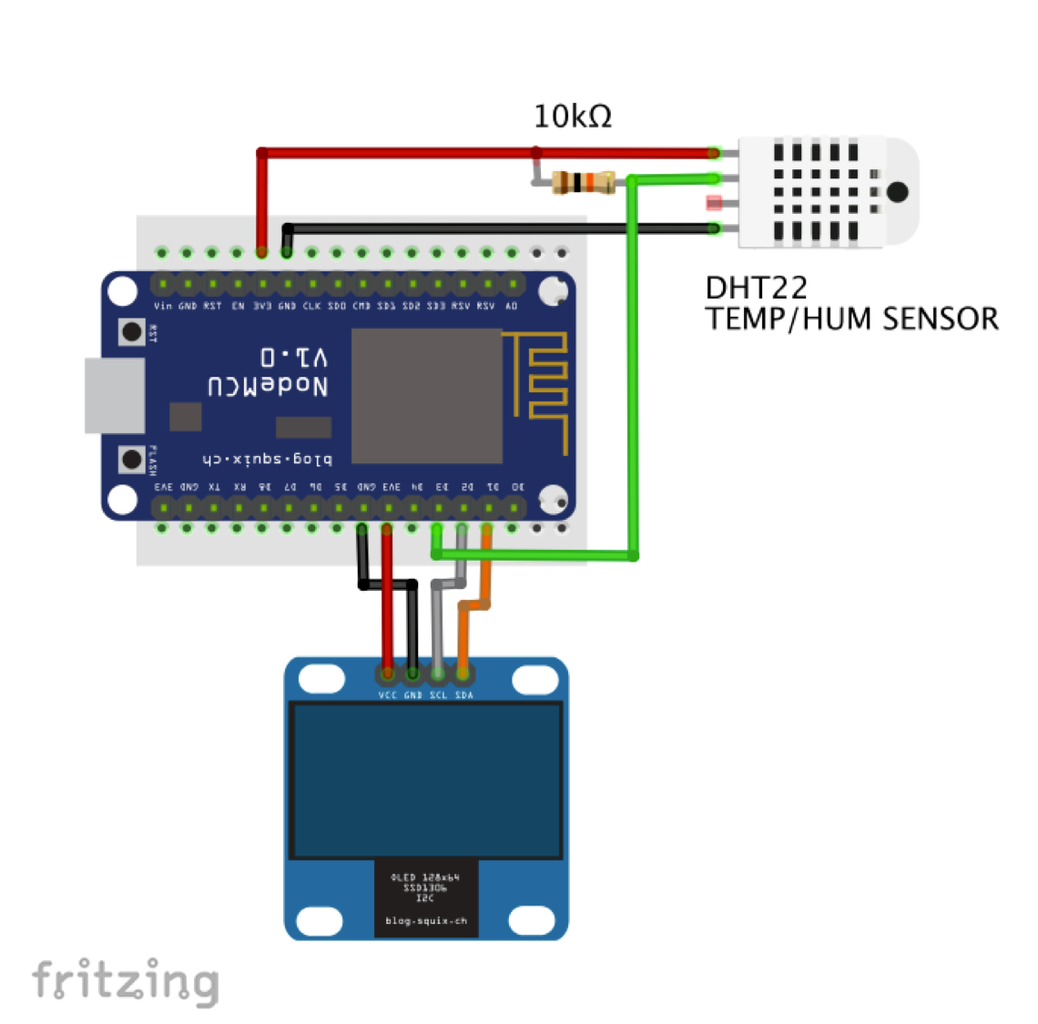
Connect the OLED pins to the NodeMCU, as described bellow and shown at above electrical diagram:
- SDA ==> D1 (5)
- SCL* ==> D2 (4) * Also you can find "SDC" in the text
- VCC ==> The SSD1306 can be powered with 5V (external) or 3.3V directly from the NodeMCU module.
- GND ==> GND
Once we have connected the display, let's download and install its library on our Arduino IDE. We have use on previous projects the ACROBOT library version, but this time we will explore another one: The "ESP8266 OLED Driver for SSD1306 display" developed by Daniel Eichhorn (Make sure that you use Version 3.0.0 or bigger!).
Bellow the library that must be downloaded and installed on your Arduino IDE:
https://github.com/squix78/esp8266-oled-ssd1306
Once you re-started the IDE, the library should be already installed.
The library supports I2C protocol to access the OLED display using the built in Wire.h library:
#include <Wire.h>
#include "SSD1306.h"
SSD1306  display(ADDRESS, SDA, SDC);
Let's list some important API that will be used with our OLED display. The complete list can be founded at the GITHub provided above.
A. Display Control:
void init(); // Initialise the display
void resetDisplay(void); // Cycle through the initialisation
void displayOn(void); // Turn the display on
void displayOff(void); // Turn the display offs
void clear(void); // Clear the local pixel buffer
void invertDisplay(void); // Inverted display mode
void normalDisplay(void); // Normal display mode
void setContrast(char contrast); // Set display contrast
void flipScreenVertically(); // Turn the display upside down
B. Pixel Drawing
void setColor(OLEDDISPLAY_COLOR color); // Sets the color of all pixel operations
void setPixel(int16_t x, int16_t y); // Draw a pixel at given position
void drawLine(int16_t x0, int16_t y0, int16_t x1, int16_t y1); // Draw a line from pos 0 to pos 1
void drawHorizontalLine(int16_t x, int16_t y, int16_t length); // Draw a line horizontally
void drawVerticalLine(int16_t x, int16_t y, int16_t length); // Draw a lin vertically
void drawFastImage(int16_t x, int16_t y, int16_t width, int16_t height, const char *image); // Draw a bitmap in the internal image format
C. Text Operations:
void drawString(int16_t x, int16_t y, String text);
// Write the text at given position
uint16_t getStringWidth(const char* text, uint16_t length);
// Returns the width of the const char* with the current font settings
uint16_t getStringWidth(String text);
// Convenience method for the const char version
void setTextAlignment(OLEDDISPLAY_TEXT_ALIGNMENT textAlignment);
// TEXT_ALIGN_LEFT, TEXT_ALIGN_CENTER, TEXT_ALIGN_RIGHT, TEXT_ALIGN_CENTER_BOTH
void setFont(const char* fontData);
// Sets the current font.

// Available default fonts: ArialMT_Plain_10, ArialMT_Plain_16, ArialMT_Plain_24
D. Frames ("Ui Library")
The Ui Library is used to provide a basic set of Ui elements called, Frames and Overlays. A Frame is used to provide information the default behaviour is to display a Frame for a defined time and than move to the next (like "Pages"). The library also provides an Indicator that will be updated accordingly. An Overlay on the other hand is a pieces of information (e.g. a clock) that is displayed always at the same position.
void init(); // Initialise the display
void setTargetFPS(uint8_t fps); //Configure the internal used target FPS
void enableAutoTransition(); //Enable automatic transition to next frame
void disableAutoTransition(); // Disable automatic transition to next frame.
void setAutoTransitionForwards(); // Set the direction if the automatic transitioning
void setAutoTransitionBackwards(); // Set the direction if the automatic transitioning
void setTimePerFrame(uint16_t time); //Set the approx. time a frame is displayed
void setTimePerTransition(uint16_t time); //Set the approx. time a transition will take
void setFrameAnimation(AnimationDirection dir); //Configure what animation is used to transition
void setFrames(FrameCallback* frameFunctions, uint8_t frameCount); //Add frame drawing functions
int8_t update();  // This needs to be called in the main loop
Once the both the OLED itself and its Library are installed, let's write a simple "Hello World program to test it. Enter with bellow code on your IDE, the result should be a display as shown at the above photo:
/* Hello World OLED Test */
#include   // Only needed for Arduino 1.6.5 and earlier
#include "SSD1306.h" // alias for `#include "SSD1306Wire.h"`
SSD1306  display(0x3c, 5, 4); // Initialise the OLED display using Wire library
void setup()
{
  Serial.begin(115200);
  display.init(); // Initialising the UI will init the display too.
  display.flipScreenVertically();

  display.clear();
  drawHelloWorld();
  display.display();
}
void loop()
{

}
void drawHelloWorld()
{
    display.setTextAlignment(TEXT_ALIGN_LEFT);
    display.setFont(ArialMT_Plain_10);
    display.drawString(0, 0, "Hello world");
    display.setFont(ArialMT_Plain_16);
    display.drawString(0, 10, "Hello world");
    display.setFont(ArialMT_Plain_24);
    display.drawString(0, 26, "Hello world");
}
Let's now, upload the sketch: SSD1306SimpleDemo.ino that is part of EXAMPLE's Library. Before run the code, change the OLED pins connection accordantly:
// Initialise the OLED display using Wire library
SSD1306  display(0x3c, 5, 4);
The video bellow shows the OLED playing the demo test code:
Step 3: Getting Indoor Data


Our NodeMCU is talking with world now! So, let's give it something real to show up! We will install a Digital Temperature/Humidity type sensor. The old and good DHTxx (DHT11 or DHT22). The ADAFRUIT site provides great information about those sensors. Bellow, some information retrieved from there:
Overview
The low cost DHT temperature & humidity sensors are very basic and slow, but are great for hobbyists who want to do some basic data logging. The DHT sensors are made of two parts, a capacitive humidity sensor and a thermistor. There is also a very basic chip inside that does some analog to digital conversion and spits out a digital signal with the temperature and humidity. The digital signal is fairly easy to read using any microcontroller.
DHT11 vs DHT22
We have two versions of the DHT sensor, they look a bit similar and have the same pinout, but have different characteristics. Here are the specs:
DHT11
- Ultra low cost
- 3 to 5V power and I/O
- 2.5mA max current use during conversion (while requesting data)
- Good for 20-80% humidity readings with 5% accuracy
- Good for 0-50°C temperature readings ±2°C accuracy
- No more than 1 Hz sampling rate (once every second)
- Body size 15.5mm x 12mm x 5.5mm
- 4 pins with 0.1" spacing
DHT22
- Low cost
- 3 to 5V power and I/O
- 2.5mA max current use during conversion (while requesting data)
- Good for 0-100% humidity readings with 2-5% accuracy
- Good for -40 to 125°C temperature readings ±0.5°C accuracy
- No more than 0.5 Hz sampling rate (once every 2 seconds)
- Body size 15.1mm x 25mm x 7.7mm
- 4 pins with 0.1" spacing
As you can see, the DHT22 is a little more accurate and good over a slightly larger range. Both use a single digital pin and are 'sluggish' in that you can't query them more than once every second (DHT11) or two (DHT22).
Both sensors will work fine to get Indoor information to be displayed on our Home Weather Station.
The DHTxx has 4 pins (facing the sensor, pin 1 is the most left) :
- VCC (we can connect to external 5V or to 3.3V from NodeMCU);
- Data out;
- Not Connected
- Ground.
Once usually you will use the sensor on distances less than 20m, a 10K ohm resistor should be connected between Data and VCC pins. The Output pin will be connected to NodeMCU pin D3 (see the diagram above).
Once the sensor is installed at our module, download the DHT library from Adafruit github repository and install it in your Arduino's Library file. Once you reload your Arduino IDE, the "DHT sensor library" should be installed.
Let's define our sensor parameters and its associated variables (we will use at first, DHT22):
/* DHT22 */
#include "DHT.h"
#define DHTPIN D3
#define DHTTYPE DHT22
DHT dht(DHTPIN, DHTTYPE);
int localHum = 0;
int localTemp = 0;
Now, let's create a function to read its data:
/***************************************************
* Get indoor Temp/Hum data
****************************************************/
void getDHT()
{
  float tempIni = localTemp;
  float humIni = localHum;
  localTemp = dht.readTemperature();
 /* for returning Fahrenheit use localTemp = dht.readTemperature(true) */
  localHum = dht.readHumidity();
  if (isnan(localHum) || isnan(localTemp))   // Check if any reads failed and exit early (to try again).
  {
    Serial.println("Failed to read from DHT sensor!");
    localTemp = tempIni;
    localHum = humIni;
    return;
  }
}
Once we have the data, let's present them on our OLED Display:
/***************************************************
* Draw Indoor Page
****************************************************/
void drawDHT()
{
  int x=0;
  int y=0;
  display.setFont(ArialMT_Plain_10);
  display.setTextAlignment(TEXT_ALIGN_LEFT);
  display.drawString(0 + x, 5 + y, "Hum");

  display.setFont(ArialMT_Plain_10);
  display.setTextAlignment(TEXT_ALIGN_LEFT);
  display.drawString(43 + x, y, "INDOOR");

  display.setFont(ArialMT_Plain_24);
  String hum = String(localHum) + "%";
  display.drawString(0 + x, 15 + y, hum);
  int humWidth = display.getStringWidth(hum);

  display.setFont(ArialMT_Plain_10);
  display.setTextAlignment(TEXT_ALIGN_LEFT);
  display.drawString(95 + x, 5 + y, "Temp");

  display.setFont(ArialMT_Plain_24);
  String temp = String(localTemp) + "°C";
  display.drawString(70 + x, 15 + y, temp);
  int tempWidth = display.getStringWidth(temp);
}
The above foto shows how the data will be shown at display.
You can download the complete code for indoor operation from my GitHub:
Home Weather Station Indoor code
Or using the file bellow:
Attachments

Step 4: Outdoor Data: Weather Underground Service

Our Outdoor weather data will be provide by a free service, the Weather Underground. You will need to create an account on their website and get an Weather API key. Do it following the instructions at bellow link:
https://www.wunderground.com/weather/api
Our Weather station is based on the great work done by Daniel Eichhorn (@squix78). Follow the instructions on his GitHub to get the appropriated Libraries. You will need at least to install the libraries bellow:
- Weather Station by Daniel Eichhorn: https://github.com/squix78/esp8266-weather-station
- Json Streaming Parser by Daniel Eichhorn: https://github.com/squix78/json-streaming-parser
After you have the libraries installed and the IDE re-started, download the program bellow from my GitHub:
MJRoBot Home Weather Station code
Once you have the code loaded on your Arduino IDE, open the "stationCredentials.h" and replace the dummy data with your personnel data:
/* WIFI */
const char* WIFI_SSID = "YOUR SSID";
const char* WIFI_PWD = "YOUR PASSWORD";

/* Wunderground Settings */
const boolean IS_METRIC = true; // use false for Fahrenheit
const String WUNDERGRROUND_API_KEY = "YOUR KEY";
const String WUNDERGRROUND_LANGUAGE = "EN";
const String WUNDERGROUND_COUNTRY = "CL";
const String WUNDERGROUND_CITY = "Santiago";
Note that the weather information that we will retrieve from W.Underground service will be regarding Santiago (the city) and CL (the country: Chile). You must also change it with your own city data.
And that's it! Your station must be running now as you can see on my prototype's photos above.
Step 5: Putting the Station in the Box

The last stage is to assemble our station on the box. I only did a simple example as shown above. I also changed the DHT22 with DHT11, only for fun
Do not forget to change the appropriate DHT declaration on file "stationDefines.h".
If you need to change the time zone, go to stationDefines.h file and change the variable UTC_OFFSET:
const float UTC_OFFSET = -3;
That's all folks!
Step 6: Conclusion

As always, I hope this project can help others find their way in the exciting world of electronics and IoT!
Please visit my GitHub for updated files:
MJRoBot Home Weather Station depository
For more projects, please visit my blog: MJRoBot.org
Saludos from the south of the world!
See you at my next instructable!
Thank you
Marcelo

Runner Up in the
Microcontroller Contest 2017

Runner Up in the
Sensors Contest 2017


