

Introduction: Keypad Door Lock


- Arduino UNO
- Breadboard
- LCD 1602 Module
- Potentiometer 10KΩ
- Servo Motor
- 4X4 Membrance Switch Module
- Buzzer
- Green LED
- Red LED
- Jumper Wires
Step 1: Add Potentiometer and LCD 1602 Module

- Connect Potentiometer to D-33, D-34, and D-35.
- Connect Jumper wire to D-33 to negative rail on Breadboard.
- Connect Jumper wire to D-35 to positive rail on Breadboard.
- Connect LCD 1602 Module to J-3 - J-18.
- Connect Jumper wire to J-3 to negative rail on Breadboard.
- Connect Jumper wire to J-4 to positive rail Breadboard.
- Connect Jumper wire to J-5 to D-34 on Breadboard.
- Connect Jumper wire to J-6 to Digital Pin 12 on Arduino .
- Connect Jumper wire to J-7 to to negative rail on Breadboard .
- Connect Jumper wire to J-8 to Digital Pin 11 on Arduino .
- Connect Jumper wire to J-13 to Digital Pin 10 on Arduino .
- Connect Jumper wire to J-14 to Digital Pin 9 on Arduino.
- Connect Jumper wire to J-15 to Digital Pin 8 on Arduino.
- Connect Jumper wire to J-16 to Digital Pin 7 on Arduino.
- Connect Jumper wire to J-17 to positive rail on Breadboard.
- Connect Jumper wire to J-18 to negative rail on Breadboard.
Step 2: Add 4X4 Membrance Switch Module

- Connect 4X4 Membrance Switch Module Pin 1 to Analog Pin A0 on Arduino.
- Connect 4X4 Membrance Switch Module Pin 2 to Analog Pin A1 on Arduino.
- Connect 4X4 Membrance Switch Module Pin 3 to Analog Pin A2 on Arduino.
- Connect 4X4 Membrance Switch Module Pin 4 to Analog Pin A3 on Arduino.
- Connect 4X4 Membrance Switch Module Pin 5 to Analog Pin A4 on Arduino.
- Connect 4X4 Membrance Switch Module Pin 6 to Analog Pin A5 on Arduino.
- Connect 4X4 Membrance Switch Module Pin 7 to Digital Pin 3 on Arduino.
- Connect 4X4 Membrance Switch Module Pin 8 to Digital Pin 2 on Arduino.
Step 3: Add Buzzer
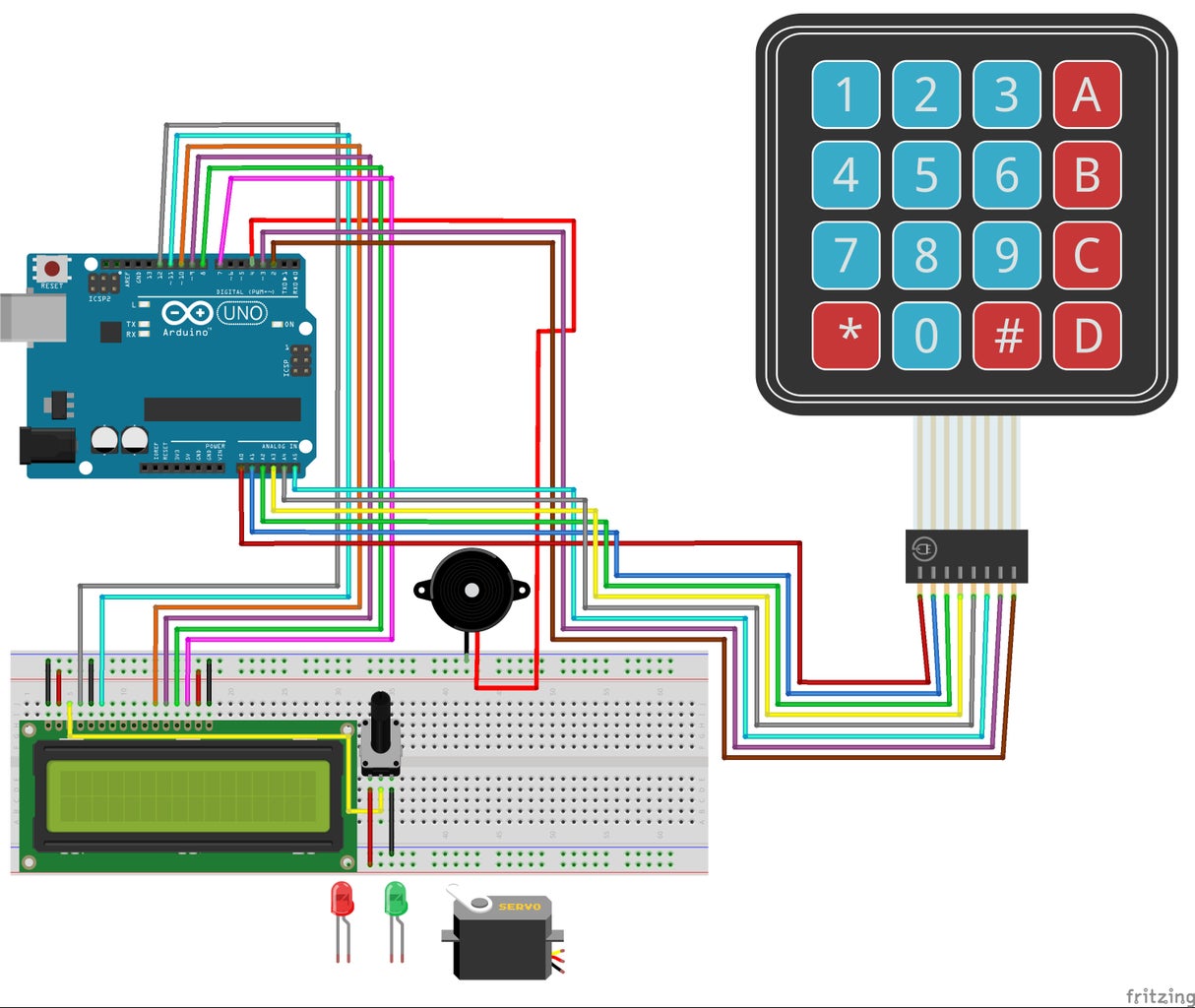
- Connect the Buzzer ground wire to the negative rail on the Breadboard.
- Connect the Buzzer positive wire to Digital Pin 4 on Arduino.
Step 4: Add Red and Green LEDs

- Connect Red LED to G-52 negative end and G-51 positive end on Breadboard.
- Connect Jumper wire to negative rail and to J-52 on Breadboard.
- Connect a Jumper wire to G-51 on Breadboard to Digital Pin 6 on Arduino.
- Connect Green LED to G-57 negative end and G-56 positive end on Breadboard.
- Connect Jumper wire to negative rail and to J-57 on Breadboard.
- Connect a Jumper wire to G-56 on Breadboard to Digital Pin 5 on Arduino.
Step 5: Add Servo Motor

Connect Servo Motor positive wire to positive rail on the Breadboard.
Connect Servo Motor ground wire to negative rail on the Breadboard.
Connect Servo Motor signal wire to Digital Pin 13 on Arduino.
Step 6: Connect Power and Ground
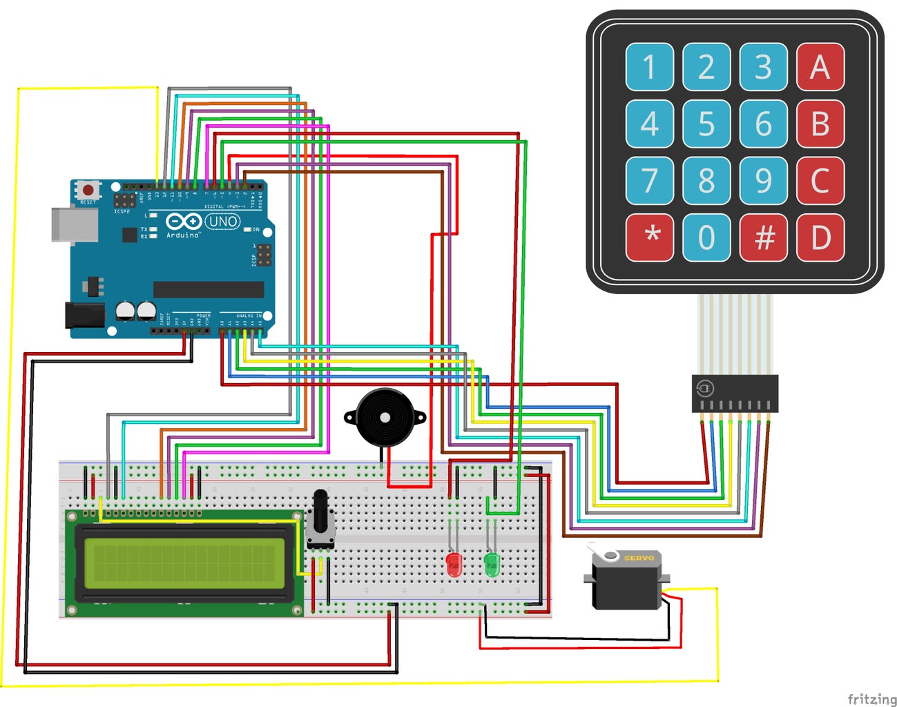
- Connect Jumper wire to 5v pin on Arduino to the positive rail on the Breadboard.
- Connect Jumper wire to GND pin on Arduino to the negative rail on the Breadboard.
- Connect Jumper wire to negative rail on the Breadboard to the other negative rail on the Breadboard.
- Connect Jumper wire to positive rail on the Breadboard to the other positive rail on the Breadboard.


